audi Workshop Repair Guides

Audi Workshop Service and Repair Manuals

Removing and installing exhaust gas temperature sender 4G648 > < Removing and installing exhaust gas temperature sender 1G235
Removing and installing exhaust gas temperature sender 3G495
Removing and installing exhaust gas temperature sender 3 -G495-
Special tools and workshop equipment required
   
t  Tool set, 17 mm -T10395-
  W00-10767
Removing
–  Remove Lambda probe -G39- → Rep. gr.23.
–  Unplug electrical connector -1- for exhaust gas temperature sender 3 -G495- and move electrical wiring clear.
  Note
Disregard -items 2, 3-.
  A26-10696
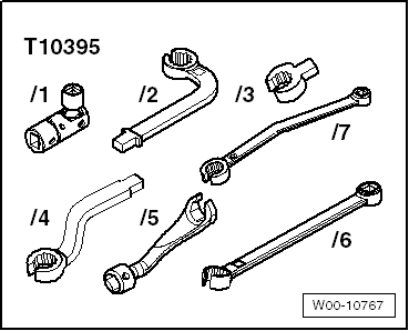
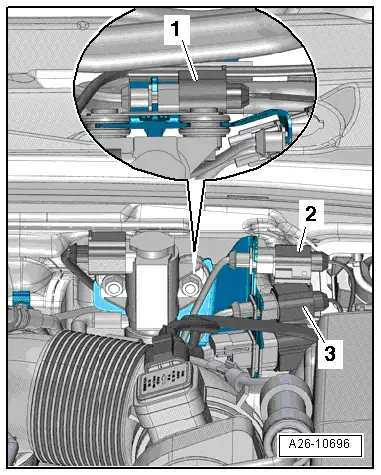
–  Unscrew exhaust gas temperature sender 3 -G495--item 1- using a tool from tool set, 17 mm -T10395-.
  Note
Disregard -items 2, 3-.
  Caution
Risk of malfunctions caused by improperly secured exhaust gas temperature senders.
The threads of the exhaust gas temperature senders -G495- and -G648- are coated. It is important that you do NOT coat them additionally with high-temperature paste and that you tighten them to the specified torque.
Installing
Installation is carried out in the reverse order; note the following:
l  Tightening torque → Chapter „Exhaust gas temperature control - exploded view“
  Note
t  Coat threads of temperature sender with high-temperature paste → Electronic parts catalogue.
t  Fit all cable ties in the original positions when installing.
  A26-10721
Installation position of exhaust gas temperature sender 3 -G495--item 1-:
l  Angled section of pipe faces towards left side of vehicle.
l  Angle -α- between pipe and marking -arrow- = approx. 17°.
–  Install Lambda probe -G39- → Rep. gr.23
–  Electrical connections and routing → Current flow diagrams, Electrical fault finding and Fitting locations.
  A26-10729

Removing and installing exhaust gas temperature sender 4G648 > < Removing and installing exhaust gas temperature sender 1G235