
A3 Mk2
 Note
Note |
|
|

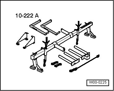
| Special tools and workshop equipment required |
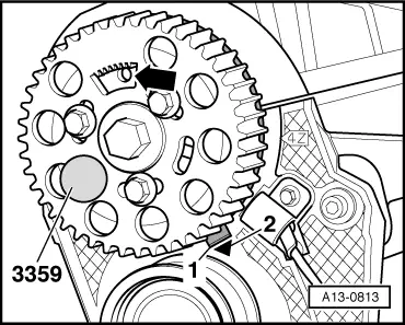
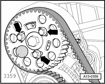
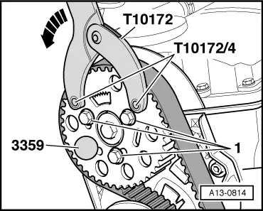
| t | Locking pin -3359- |
| t | Engine bung set -VAS 6122- |
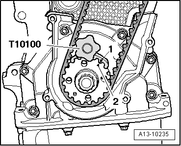
| t | Crankshaft stop -T10100- |
| t | Counter-hold tool -T10172- with pin -T10172/4- |
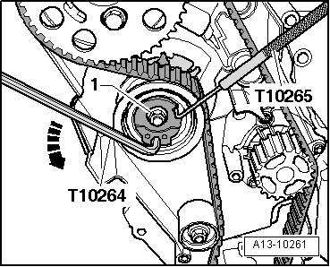
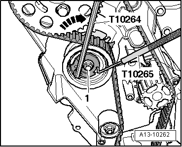
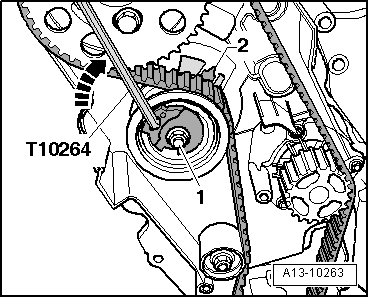
| t | Angle driver -T10264- |
| t | Locking tool -T10265- |
|
|
|
|
|
|
|
|
 WARNING
|
|
|
|
|
|
|
|
|
|
|
|
|
|
|
|
|
|
|
|
|
|
|
|
Note
|
|
Note
Note
|
|
 Caution
Note
|
|
|
|
|
|
|
|
|
|
Note
Note
|
|
|
|
|
|
Note
|
|
Note
|
|
| Component | Nm | ||
| Tensioning roller for toothed belt to cylinder head | 20 + 45° | ||
| Camshaft sprocket to hub | 25 | ||
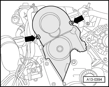
| Toothed belt cover (bottom) to cylinder block | 10 1) | ||
| Toothed belt cover (centre) to cylinder block | 10 1) | ||
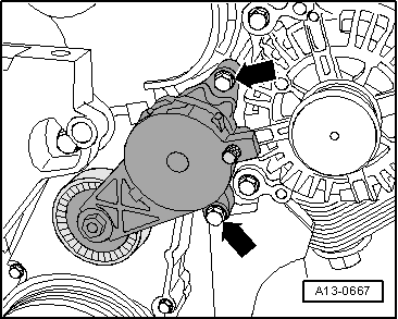
| Tensioner for poly V-belt to bracket for ancillaries | 23 | ||
| Air pipe (right-side) to bracket | 8 | ||
| |||