
A3 Mk2
|
|
|
|
|
|
|
|
|
|
|
 Caution
 WARNING
|
|
|
|
|
|
|
|
|
|
|
|
|
|
|
|
|
|
|
|
|
|
|
|
|
|
 Note
Note
|
|
|
|
|
|
|
|
|
|
|
|
|
|
Note
Note
|
|
| Component | Nm | ||
| Oil return pipe to turbocharger | 15 | ||
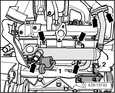
| Exhaust gas recirculation cooler to: | Intake manifold | 22 | |
| Cylinder block | 10 | ||
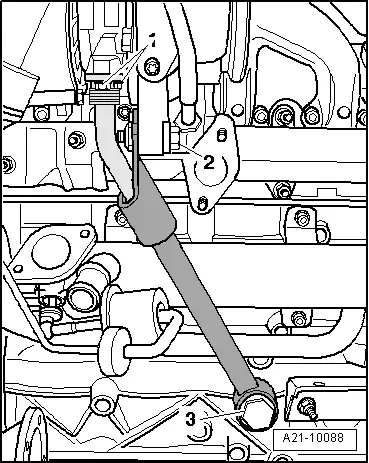
| Support for turbocharger to: | Turbocharger | 25 | |
| Cylinder block | 60 | ||
| EGR connecting pipe to: | Exhaust gas recirculation cooler | 22 | |
| Exhaust manifold | 25 | ||
| Underbody cross member (front) to body | 23 | ||
| Air pipe (left-side) to bracket | 8 | ||