audi Workshop Repair Guides

Audi Workshop Service and Repair Manuals

Drive chain for valve gear - exploded view > < Camshaft timing chain - exploded view
Removing and installing camshaft timing chain
   
Removing and installing camshaft timing chain
Special tools and workshop equipment required
t  Torque wrench -V.A.G 1331-
t  Open ring spanner insert -V.A.G 1332/9-
t  Socket -T03003-
t  Locking pin -T03006-
t  Locking pin -T40069-
t  Camshaft clamp -T40070-

   
t  Key -T40079-
  W00-10334
Removing
–  Remove noise insulation -1- → Rep. gr.66.
–  Remove vacuum pump → Rep. gr.47.
–  Remove cylinder head cover → Chapter.
–  Remove timing chain cover (top) → Chapter.
  A10-10917
–  Turn crankshaft with socket -T03003- in normal direction of rotation -arrow- to „TDC position“.
l  Notch -1- in socket -T03003- must be perpendicular to sealing surface of sump.
l  Marking -2- on vibration damper must be opposite marking -3- on sealing flange.
  A15-10664
l  The threaded holes -arrows- in the camshafts must face upwards.
  Note
Turn crankshaft by 360° if the threaded holes do not point upwards.
  A15-10665
–  Fit camshaft clamp -T40070- onto cylinder head and tighten bolts -arrows- to 25 Nm.
l  The camshaft clamp -T40070- is positioned correctly if the holes for the cylinder head bolts remain free.
  A15-10666
–  Unscrew plug -arrow- for „TDC“ marking from cylinder block.
  A15-10667
–  Screw locking pin -T40069- into locating groove and tighten to 15 Nm. If necessary, turn crankshaft backwards and forwards slightly to fully centralise locking pin.
  A15-10668
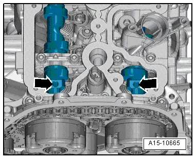
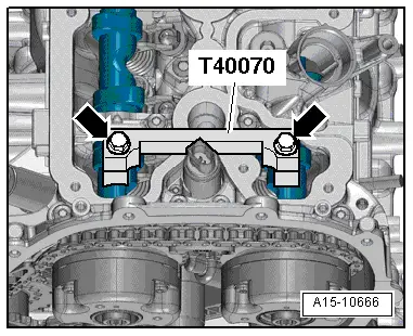
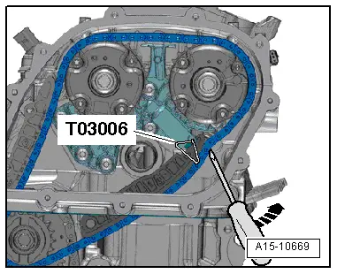
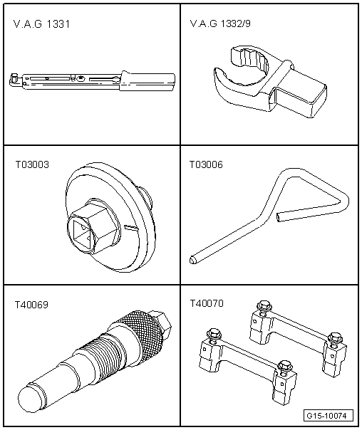
–  Press guide rail of chain tensioner for camshaft timing chain inwards as far as the stop using a screwdriver. Then lock chain tensioner by inserting locking pin -T03006-.
  Caution
If a used timing chain rotates in the opposite direction when it is refitted, this can cause breakage.
Mark running direction of timing chain with coloured arrows for re-installation. Do not mark timing chain by means of centre punch, notch or the like.
Risk of irreparable damage to engine.
Block off the opening in the valve timing housing with a clean cloth to prevent small items from dropping into the engine.
  A15-10669
–  Unscrew bolts -1- and -2- and detach both camshaft adjusters.
  A15-10670
–  Detach camshaft timing chain from drive sprocket -arrow- for camshaft timing chain.
Installing
l  Tightening torques → Chapter „Camshaft timing chain - exploded view“
  Note
Renew the bolts tightened with specified tightening angle.
  Caution
Avoid damage to valves and piston crowns.
The crankshaft must not be at „TDC“ at any cylinder when the camshafts are turned.
  A15-10674
l  Drive chain for valve gear installed → Chapter
l  Crankshaft locked in position with locking pin -T40069-.
  A15-10668
l  Camshaft clamp -T40070- installed and tightened to 25 Nm -arrows-.
  A15-10666
–  Fit camshaft timing chain onto drive sprocket -arrow- for camshaft timing chain.
  A15-10674
–  Install camshaft adjusters according to marks applied when removing → Item and → Item.
–  Attach camshaft adjusters with camshaft timing chain fitted, fit bolts -1- and -2- without tightening.
l  It should just be possible to turn both camshaft adjusters on the camshaft without axial movement.
–  Remove locking pin -T03006-.
  Note
  A15-10670
A second mechanic is required for the following work steps.
–  Fit key -T40079- onto camshaft adjuster of exhaust camshaft.
–  Apply torque wrench -V.A.G 1331- with open ring spanner insert -V.A.G 1332/9- to key -T40079-.
–  Have a 2nd mechanic apply a torque of 25 Nm to camshaft adjuster in clockwise direction -arrow-.
–  Tighten bolts as follows while keeping camshaft adjuster under tension:
  A15-11192
StageBoltTightening torque
1.-1-on inlet camshaft 60 Nm
1.-2-on exhaust camshaft 60 Nm

–  Remove key -T40079-.
   
–  Remove camshaft clamp -T40070--arrows-.
  A15-10666
–  Tighten bolts for camshaft adjusters in the following sequence:
  A15-10670
StageBoltAngle to turn bolts
2.-1-90°
2.-2-90°

   
–  Remove locking pin -T40069-.
  A15-10668
–  Using socket -T03003-, turn crankshaft two rotations in normal direction of rotation -arrow- until crankshaft is at „TDC“ again.
l  Notch -1- in socket -T03003- must be perpendicular to sealing surface of sump.
l  Marking -2- on vibration damper must be opposite marking -3- on sealing flange.
  Note
If you turn the crankshaft beyond „TDC“ by mistake, turn it back approx. 30° and set to „TDC“ again.
  A15-10664
l  The threaded holes -arrows- in the camshafts must face upwards.
  Note
Turn crankshaft by 360° if the threaded holes do not point upwards.
  A15-10665
–  Fit camshaft clamp -T40070- and tighten bolts -arrows- to 25 Nm.
l  The camshaft clamp -T40070- is positioned correctly if the holes for the cylinder head bolts remain free.
  A15-10666
–  Screw locking pin -T40069- into locating groove and tighten to 15 Nm.
l  The locking pin -T40069- must engage in the groove in the crankshaft. If it does not, reset valve timing.
–  Remove camshaft clamp.
–  Remove locking pin.
Remaining installation steps are carried out in reverse sequence; note the following:
–  Tighten plug for „TDC“ marking → Fig..
–  Install timing chain cover (top) → Chapter.
–  Install cylinder head cover → Chapter.
–  Install vacuum pump → Rep. gr.47.
–  Install noise insulation → Rep. gr.66.
  A15-10668

Drive chain for valve gear - exploded view > < Camshaft timing chain - exploded view