
A3 Mk2
| Removing and installing coolant pump |

| Special tools and workshop equipment required |
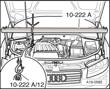
| t | Support bracket -10-222 A- |
| t | Shackle -10-222 A/12- |
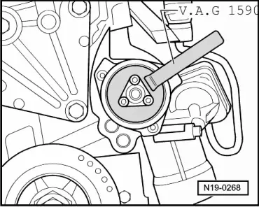
| t | Water pump spanner -V.A.G 1590- |
| t | Hose clip pliers -V.A.G 1921- |
| t | Drip tray for workshop hoist -VAS 6208- |
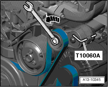
| t | Locking pin -T10060 A- |
| t | Bolt M8x40 |
 Note
Note |
 WARNING
|
|
|
|
|
|
|
|
|
|
|
|
|
|
Note
|
|
|
|
|
|
Note
|
|
Note
|
|
|
|
| Component | Nm |
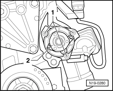
| Coolant pump to cylinder block | 8 |
| Pulley to coolant pump | 20 |