audi Workshop Repair Guides

Audi Workshop Service and Repair Manuals

High-pressure pump - exploded view > < Checking fuel pressure (low pressure) up to high-pressure pump
Checking fuel pressure and residual pressure (up to high-pressure pump)
   
Checking fuel pressure and residual pressure (up to high-pressure pump)
Special tools and workshop equipment required
t  K-Jetronic pressure tester -V.A.G 1318-
t  Adapter -V.A.G 1318/11-
t  Adapter -V.A.G 1318/17-1- from adapter set -V.A.G 1318/17-
t  Connector -V.A.G 1318/23-
t  Remote control -V.A.G 1348/3 A- with adapter cable -V.A.G 1348/3-3-
t  Auxiliary measuring set -V.A.G 1594 C- or -V.A.G 1594 A-
t  Fuel-resistant measuring container

Test conditions
l  Battery voltage at least 12.5 V
l  Fuel filter OK
l  Fuel tank at least 1/4 full.
l  Fuel pump control unit -J538- OK (check)
l  Ignition off.
   
Test sequence
–  Remove rear seat → General body repairs, interior; Rep. Gr.72.
–  Unclip the retaining tabs -arrows- for the flange cover.
  A20-1206
–  Unplug electrical connector -arrow- at flange.
  A20-1067
–  Connect remote control -V.A.G 1348/3 A- with adapter cable -V.A.G 1348/3-3- to contact -1- using a test lead from auxiliary measuring set -V.A.G 1594 C-.
–  Tape off 2nd connector contact of the adapter cable -V.A.G 1348/3-3- with insulating tape -arrow- to prevent short circuits.
–  Connect contact -5- to the body (earth) using a test lead from auxiliary measuring set -V.A.G 1594 C-.
–  Connect crocodile clamp to positive (+) terminal of battery.
–  Remove filler cap from fuel filler neck.
  WARNING
Fuel system is pressurised (low pressure). Wear safety goggles and protective clothing to avoid possible injury and skin contact. Before opening the fuel system, wrap a cloth around the connection. Then dissipate pressure by carefully detaching the connection.
  A20-1120
–  Disconnect fuel supply pipe -3- (lift release tab).
  Note
The fuel return pipe -2- and vacuum pipe -1- remain connected (if fitted).
  A20-1121
–  Connect K-Jetronic pressure tester -V.A.G 1318- with suitable adapter at fuel supply pipe connection.
–  Run test hose -arrow- into measuring container.
–  Open cut-off valve on K-Jetronic pressure tester -V.A.G 1318-. Lever must point in direction of flow.
–  Bleed fuel system by pressing remote control button briefly.
  A20-1122
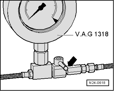
–  Close cut-off valve on K-Jetronic pressure tester -V.A.G 1318-. Lever is at right angle to direction of flow -arrow-.
  Note
Cut-off valve on K-Jetronic pressure tester -V.A.G 1318- must be on the side leading to measuring container.
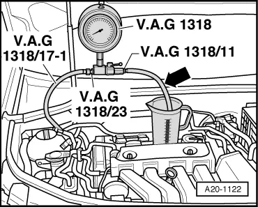
–  Press and hold remote control switch until pressure tester -V.A.G 1318- shows no further increase in pressure.
l  Specification: approx. 6 bar (4 ... 8 bar).
If specification is not obtained:
–  Check delivery rate of fuel pump → Fuel supply system, petrol engines; Rep. Gr.20.
Checking residual pressure
–  Check leak-tightness and residual pressure by watching the drop in pressure on the K-Jetronic pressure tester -V.A.G 1318-.
l  After 10 minutes pressure should still be at least 3 bar.
If the residual pressure drops below 3 bar:
t  Check union between pressure tester -V.A.G 1318- and fuel supply line for leaks.
t  Check pressure tester -V.A.G 1318- for leaks.
t  Check fuel lines and their connections for leaks.
t  Renew fuel filter with integrated fuel pressure regulator → Fuel supply system, petrol engines; Rep. Gr.20. Then repeat the test.
t  If fuel filter is OK, renew fuel pump → Fuel supply system, petrol engines; Rep. Gr.20.
Assembly is carried out in the reverse order; note the following:
  N24-0618
–  The ignition must be switched off.
  Note
Before removing the pressure tester, release the fuel pressure by opening the cut-off valve. Hold end of test hose in a container.
–  Re-install fuel supply line (make sure that all parts are clean).
  A20-1122

High-pressure pump - exploded view > < Checking fuel pressure (low pressure) up to high-pressure pump