| –
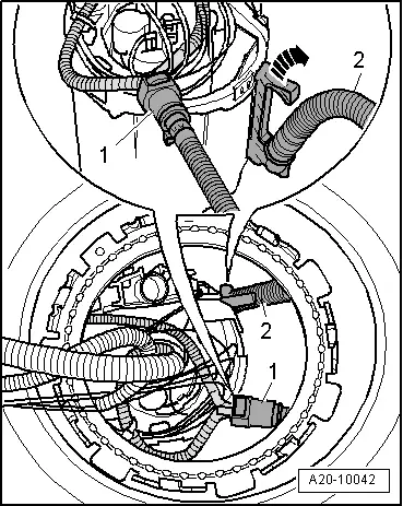
| In opening in fuel tank, press release tab to disconnect supply line -1- to suction-jet pump. |
| –
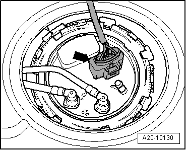
| Pull up retaining tab -arrow- and disengage fuel supply line -2- at fuel delivery unit. |
| –
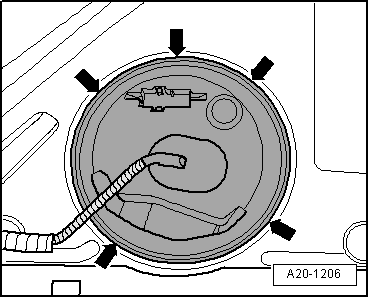
| Remove fuel delivery unit. |

Note | t
| When removing fuel delivery unit, make sure you do not bend float arm of fuel gauge sender -G-. |
| t
| Keep in mind that the fuel delivery unit still contains fuel. |
| Installation is carried out in the reverse order; note the following: |
Note | t
| Take care not to bend the fuel gauge sender -G- when fitting the fuel delivery unit. |
| t
| Ensure that fuel hoses are securely seated. |
| –
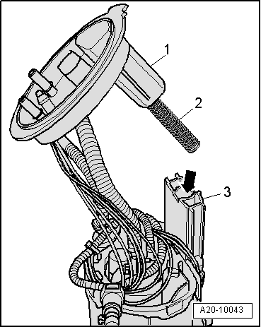
| Insert fuel delivery unit into fuel tank, with flange set aside. |
| –
| Fit fuel supply line -2- onto fuel delivery unit so that it engages audibly. |
| –
| Fit supply line -1- leading to suction-jet pump so that it engages audibly. |
|
|
|
 WARNING
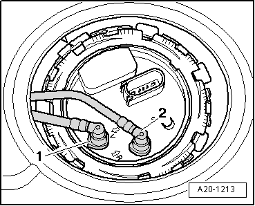
 Caution