audi Workshop Repair Guides

Audi Workshop Service and Repair Manuals

Removing and installing tandem pump - vehicles with 4-valve engine > < Checking tandem pump - vehicles with 4-valve engine
Removing and installing tandem pump - vehicles with 2-valve engine
Special tools and workshop equipment required
   
t  Hose clip pliers -V.A.G 1921-
  W00-0464
t  Diesel extractor -VAS 5226-
  W00-1187
Removing
Observe safety precautions → Chapter.
Observe rules for cleanliness → Chapter.
Engine cover panel (version 1):
–  Lift engine cover panel at the sides -arrows 1- and pull off towards the front -arrow 2-.
  A10-1855
Engine cover panel (version 2):
–  Lift off engine cover panel (outside -1- and inside -2-) by pulling up evenly.
  A10-10366
All vehicles (continued):
–  Pull cover off air duct (release clips on sides) -arrows-.
  A10-10367
–  Unclip air duct at the bottom by releasing clips -arrows-.
–  Detach air duct (bottom) together with air hose.
  A10-10368
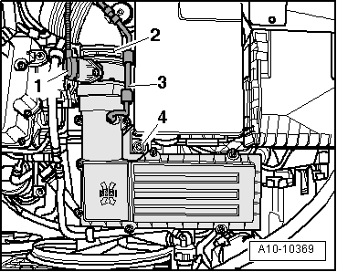
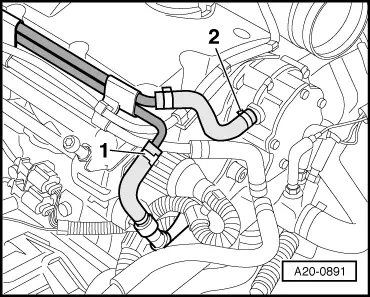
–  Unplug electrical connector -1- at air mass meter -G70-.
–  Detach vent hose -3- and air hose -2-.
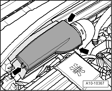
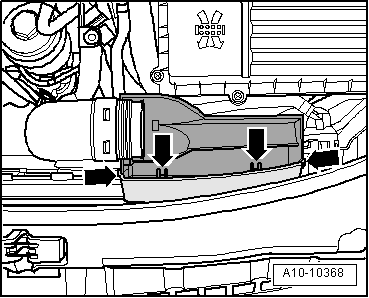
–  Unscrew bolt -4- and remove air cleaner housing.
  WARNING
t  
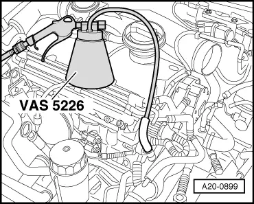
The fuel system is pressurised. Wrap a cloth around the connection before opening the system. Then release pressure by carefully loosening the connection.
t  In extreme cases the temperature of the fuel lines and the fuel can be up to 100 °C after the engine is switched off. Allow the fuel to cool down before disconnecting the lines - danger of scalding.
t  Wear protective gloves.
t  Wear safety goggles.
  A10-10369
–  Disconnect fuel supply hose -2- from tandem pump.
–  Disconnect fuel return hose -1- (blue marking) from fuel pipe.
  A20-0891
–  Connect compressed air line to diesel extractor -VAS 5226-.
–  Connect diesel extractor -VAS 5226- to fuel return hose.
  Note
Empty the bleeder container before it becomes full. Do not allow fuel to enter hand vacuum pump.
–  Operate diesel extractor -VAS 5226- until no more fuel comes out of return hose.
  A20-0899
–  Detach vacuum hose -arrow- going to brake servo at tandem pump.
  A10-1851
–  Remove bolts -arrows-.
–  Remove tandem pump from cylinder head.
Installing
Installation is carried out in the reverse order; note the following:
  Note
t  Secure all hose connections with the correct type of hose clips (same as original equipment) → Electronic parts catalogue.
t  Renew tandem pump gaskets.
t  Ensure proper seating of tandem pump actuator in camshaft.
–  Install tandem pump and tighten top securing bolts to 20 Nm.
–  Tighten bottom securing bolts to 10 Nm.
–  Connect all hoses to tandem pump.
  A20-0611

Removing and installing tandem pump - vehicles with 4-valve engine > < Checking tandem pump - vehicles with 4-valve engine