audi Workshop Repair Guides

Audi Workshop Service and Repair Manuals

Removing and installing Lambda probes (before catalytic converter) > < Removing and installing injectors
Checking injection quantity and spray pattern of injectors; checking for leaks
   
Checking injection quantity and spray pattern of injectors; checking for leaks
Special tools and workshop equipment required
t  Remote control -V.A.G 1348/3 A- with adapter cable -V.A.G 1348/3-2-
t  Auxiliary measuring set -V.A.G 1594 C- or -V.A.G 1594 A-
t  Adapter cable -V.A.G 1598/31- (test box)
t  Injection rate tester -V.A.G 1602-

Test condition
l  Fuel pressure OK; testing → Chapter.
Test sequence
–  Remove intake manifold → Chapter.
–  Remove fuel rail together with injectors → Chapter. Fuel hose remains connected.
   
Checking for leaks
–  Open lid of electronics box in engine compartment and remove fuse SB33.
–  Connect remote control -V.A.G 1348/3 A- with adapter cable -V.A.G 1348/3-2- to fuse contact for fuel pump and to the positive (+) battery terminal.
–  Connect battery earth cable.
–  Press button on remote control -V.A.G 1348/3 A-.
l  The fuel pump should run.
–  Visually check the fuel injectors for leaks.
l  When the fuel pump is running, no more than 1 to 2 drops a minute should escape from any one of the injectors.
If the fuel loss is greater:
–  Renew defective fuel injector → Chapter.
–  Re-insert fuse SB33 in electronics box in engine compartment.
Checking injection quantity
–  Connect adapter cable -V.A.G 1598/31- (test box) to wiring harness for engine control unit → Chapter. The engine control unit is not connected.
–  Use leads from adapter set -V.A.G 1594 C- to bridge contacts 1 and 65 at test box.
–  Unplug electrical connectors for injectors.
–  Place a fuel injector in a measuring glass for injection rate tester -V.A.G 1602-.
  A97-0973
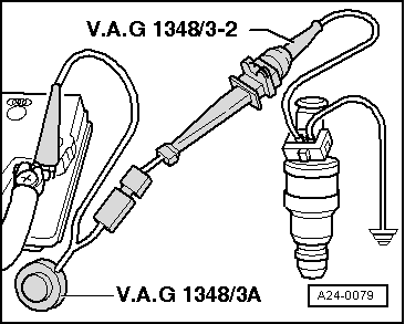
–  Connect one of the contacts of the fuel injector to engine earth (–) using test lead and crocodile clamp from adapter set -V.A.G 1594 C-.
–  Connect second contact of fuel injector to remote control -V.A.G 1348/3 A- using adapter cable -V.A.G 1348/3-2-.
–  Connect crocodile clamp to positive (+) battery terminal.
–  Use leads from adapter set -V.A.G 1594 C- to bridge contacts 1 and 65 at test box.
–  If necessary, connect battery earth cable.
–  Switch on ignition.
l  The fuel pump should run.
–  Press button on remote control -V.A.G 1348/3 A- for 30 seconds.
–  Carry out test for all fuel injectors using a new test glass each time.
  Note
Also check the spray pattern when testing the injection rate. The spray pattern should be the same for all injectors.
–  Once all 6 injectors have been actuated, place measuring glasses on a level surface.
l  Specification: 128 ... 140 ml for each injector
If the measured values for one or more of the fuel injectors do not meet the specification:
–  Switch off fuel pump (switch off ignition) and renew defective injector → Chapter.
If the measured values for all the injectors are outside the specification:
–  Check fuel pressure → Chapter.
–  Install injectors together with fuel rail → Anchor.
–  Install intake manifold → Chapter.
  A24-0079

Removing and installing Lambda probes (before catalytic converter) > < Removing and installing injectors