audi Workshop Repair Guides

Audi Workshop Service and Repair Manuals

Dismantling and assembling fuel rail with injectors (engine code BAG) > < Checking operation of air flow control flaps
Removing and installing intake manifold
   
Removing
–  Unclip air intake hose from air duct -arrows-.
  A10-10006
–  Unplug electrical connector -2- at intake air temperature sender 2 -G299-.
–  Detach vacuum hose -1- from actuator for intake air preheater.
  A10-10007
–  Pull dipstick -1- out of guide tube.
–  Remove the engine cover together with air cleaner housing -arrows-.
–  Re-insert dipstick in guide tube.
  A10-10008
–  Unplug electrical connector at solenoid valve 1 for activated charcoal filter system -N80-.
  A24-0845
–  Unplug electrical connector -1- at throttle valve module -J338-.
–  Unscrew bolts -arrows- and remove throttle valve module -J338-.
  A15-1079
–  Remove bolts -arrows- for connecting pipe for exhaust gas recirculation at exhaust gas recirculation valve -N18- and remove gasket.
  A26-10010
–  Detach vacuum hose -1- leading to solenoid valve 1 for activated charcoal filter system -N80- at intake manifold.
–  Detach solenoid valve 1 for activated charcoal filter system -N80- from its retainers and move to side with vacuum hoses attached.
–  Detach vacuum line -2- leading to brake servo at intake manifold.
–  Unclip upper coolant pipe at intake manifold -arrows- and move forward.
  A15-1080
–  Disconnect hose -2- for crankcase breather system at intake manifold by pressing release tabs.
–  Unplug electrical connectors at intake manifold pressure sender -G71--item 1- and intake manifold flap air flow control valve -N316--item 3-.
  A15-1077
–  Disconnect vacuum hose -arrow- at actuator for intake manifold change-over.
–  Unscrew securing bolts -1- and -2- for intake manifold and lay intake manifold to rear.
  A15-10020
–  Unplug electrical connector -arrow- at bolt.
–  Unscrew fuel pressure sender -G247-.
–  Lift intake manifold up and towards left.
Installing
  Note
t  Make sure that no dirt etc. gets into the opened intake manifold.
t  Renew gaskets and seals.
t  Secure all hose connections with the correct type of hose clips (same as original equipment) → Parts catalogue.
–  Place intake manifold rearwards in engine compartment for the meantime.
–  Screw in fuel pressure sender -G247-.
–  Secure intake manifold to cylinder head.
Remaining installation steps are carried out in reverse sequence; note the following:
Tightening torques
  A15-10021
ComponentNm
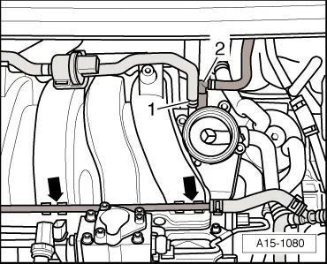
Intake manifold to fuel rail (bottom section of intake manifold)20
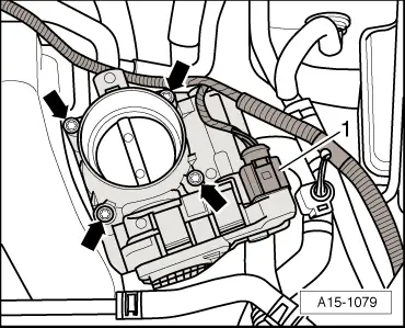
Throttle valve connection to intake manifold7
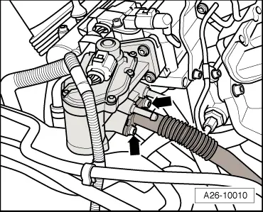
EGR connecting pipe to exhaust gas recirculation valve -N18-8


Dismantling and assembling fuel rail with injectors (engine code BAG) > < Checking operation of air flow control flaps