| t
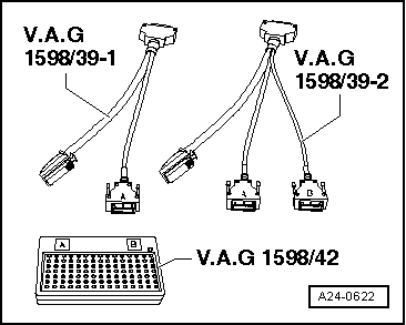
| If a wiring connection leads to the 94-pin connector (according to current flow diagram), then connect the larger of the two connectors using adapter cable -V.A.G 1598/39–2- as follows: The connector marked “A” must be attached to connection “A” on the test box -V.A.G 1598/42- and the connector marked “B” must be attached to connection “B” on the test box -V.A.G 1598/42-. |
| t
| The test box -V.A.G 1598/42- is designed so it can be connected both to the wiring harness for the engine control unit and to the engine control unit itself at the same time. |
| t
| The advantage of this is that the electronic engine control system remains fully functional when the test box is connected (for example, for measuring signals when the engine is running). |
| t
| The relevant test procedure will state whether it is necessary to also connect the engine control unit to the test box. |

WARNING | To prevent damage to the electronic components, select appropriate measuring range before connecting the measuring cables and observe the test requirements. |
|
| –
| Remove Motronic control unit -J220- → Chapter. |
| –
| Connect test box -V.A.G 1598/42- to wiring harness connector. The earth clip on the test box must be connected to the negative battery terminal. The instructions for performing the individual tests indicate whether or not the engine control unit itself also needs to be connected to the test box. |
| –
| Carry out test as described in appropriate repair procedures. |
| Installing engine control unit |
| Installation is performed in the reverse sequence; the engine control unit must be installed with the protective housing. New shear bolts must be used. |
| Perform the following after reconnecting engine control unit: |
|
|
|
 Note
Note