
A3 Mk2
|
|
|
|
|
|
|
 Note
Note
|
|
|
|
|
|
|
|
|
|
Note
|
|
|
|
|
|
|
|
|
|
Note
|
|
|
|
|
|
|
|
|
|
|
|
Note
|
|
|
|
| Component | Nm | |||||
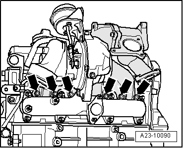
| Intake manifold to cylinder head | 22 | |||||
| Exhaust gas recirculation cooler to intake manifold | 22 | |||||
| Heat shield to exhaust manifold | 25 | |||||
| Support for turbocharger to: | Cylinder block | 60 | ||||
| Turbocharger | 25 | |||||
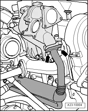
| Oil pipe to turbocharger | 15 | |||||
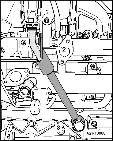
| Pendulum support to: | Gearbox | 40 + 90° 1)2) | ||||
| Subframe | 100 + 90° 1)2) | |||||
| Drive shaft heat shield to cylinder block | 35 | |||||
| Exhaust gas recirculation valve -N18- to intake manifold | 10 | |||||
| Intake manifold flap motor -V157- to intake manifold | 10 | |||||
| Air pipe to bracket | 10 | |||||
| ||||||