audi Workshop Repair Guides

Audi Workshop Service and Repair Manuals

Removing and installing diesel direct injection system control unit J248 > < Removing and installing electrical wiring harness for unit injectors
Wiring and component check with test boxV.A.G 1598/42
Wiring and component check with test box -V.A.G 1598/42-
  Note
   
t  
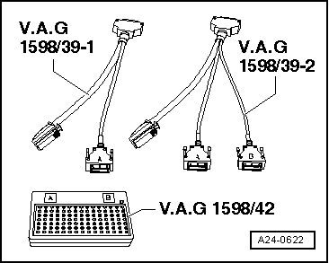
The test box -V.A.G 1598/42- has 105 sockets. It can be connected to the engine control unit via 2 different adapter leads.
t  The engine control unit is connected to the vehicle's wiring harness via two connectors, one of which has 60 pins, the other has 94 pins.
t  To carry out tests on the 60-pin wiring harness connector, the adapter lead -V.A.G 1598/39-1- is connected to connector -A- on the test box. For components connected to 60-pin wiring harness connector → Current flow diagrams, Electrical fault finding and Fitting locations.
t  To carry out tests on the 94-pin wiring harness connector, the adapter lead -V.A.G 1598/39-2- must be connected to connectors -A- and -B- on the test box. For components connected to 94-pin wiring harness connector → Current flow diagrams, Electrical fault finding and Fitting locations.
t  The test box -V.A.G 1598/42- is designed so it can be connected both to the wiring harness for the engine control unit and to the engine control unit itself at the same time. The advantage of this is that the electronic engine control system remains fully functional when the test box is connected (for example, for measuring signals when the engine is running).
t  The instructions for performing the individual tests indicate whether or not the engine control unit itself also needs to be connected to the test box.
t  Always use auxiliary measuring set -V.A.G 1594C- to connect test equipment (e.g. voltage tester -V.A.G 1527B-, hand-held multimeter -V.A.G 1526C- etc.).
The engine control unit has to be removed before connectors can be unplugged from engine control unit → Chapter.
  WARNING
To prevent damage to electronic components, select appropriate measuring range before connecting measuring leads and observe test requirements.
  A24-0622
–  Connect the test box -V.A.G 1598/42- to wiring harness with adapter lead -V.A.G 1598/39-1- or adapter lead -V.A.G 1598/39-2-. Connect earth clip of test box to negative terminal of battery. The instructions for performing the individual tests indicate whether or not the engine control unit itself also needs to be connected to the test box.
–  Carry out test as described in relevant repair procedure.
–  After completing tests re-install engine control unit → Chapter.
–  After re-connecting engine control unit, interrogate fault memory and erase it as necessary → Vehicle diagnosis, testing and information system VAS 5051.
  A24-0622

Removing and installing diesel direct injection system control unit J248 > < Removing and installing electrical wiring harness for unit injectors