audi Workshop Repair Guides

Audi A3 Workshop Service and Auto Repair Manuals

Wiring and component check with test box V.A.G 1598/42 > < Electrical wiring harness for unit injectors and glow plugs - exploded view
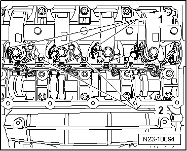
Removing and installing electrical wiring harness for unit injectors and glow plugs
Special tools and workshop equipment required
   
t  Special wrench -T10310-
  W00-10330
t  Puller -T10312-
Removing
–  Remove top section of air cleaner housing → Chapter „Removing and installing air filter element“.
–  Remove cylinder head cover → Rep. Gr.15.
  W00-10332
–  To unplug multi-pin connector for unit injectors and glow plugs, pull release pin -arrow 1- and slacken knurled nut -arrow 2-.
  Note
Puller -T10312- must be used to unplug electrical connectors on piezo unit injectors.
  A15-0912
–  Working from the side, slide puller -T10312- onto electrical connector on unit injector and pull off connector -arrow-.
  Caution
Only slacken or tighten the bolts at the retaining clips when removing and installing the electrical wiring harness. If the electrical wiring harness is released at the retaining clips, the clips will become bent and this may lead to a break in the wiring because of the increased amount of play.
  N23-10093
–  Unplug electrical connectors on glow plugs -1-.
–  Remove bolts -2- at retaining clips and detach entire electrical wiring harness.
  N23-10094
–  Apply special wrench -T10310- to adapter ring and slacken by turning 90° in anti-clockwise direction -arrow-.
  N23-10095
–  Pull retaining clip -1- slightly upwards using a screwdriver and push through main connector -2- towards inside.
Installing
–  Insert wiring harness and tighten bolts at retaining clips.
  N23-10086
–  Guide main connector through opening in bearing frame.
–  Fit retaining clip.
l  The lugs -arrows- must return to the position as shown in illustration.
  N23-10088
–  Fit adapter ring at main connector -arrow A-.
l  Long green line -2- faces upwards.
–  Tighten adapter ring with special wrench -T10310- by turning 90° in clockwise direction -arrow B-.
l  Short green line -1- now faces upwards.
Remaining installation steps are carried out in reverse sequence; note the following:
–  Install cylinder head cover → Rep. Gr.15.
Tightening torque
  A23-10155
ComponentNm
Electrical wiring harness to cylinder head10


Wiring and component check with test box V.A.G 1598/42 > < Electrical wiring harness for unit injectors and glow plugs - exploded view