
A3 Mk2
|
| Grease | Outer joint Ø | Inner joint Ø |
| G 000 603 | 90 mm | 100 mm |
| Total quantity | 120 g | 110 g |
| In joint | 80 g | 50 g |
| In boot | 40 g | 60 g |
 Note
Note
|

| 1 - | Outer constant velocity joint |
| q | Renew only as complete unit |
| q | Checking → Chapter |
| q | Removing → Fig. |
| q | Greasing ⇒ see table → Anchor |
| q | Installing → Anchor |
| q | Grease splines on drive shaft lightly with grease used in joint when fitting joint onto drive shaft |
| 2 - | Bolt |
| q | Always renew if removed |
| q | Different versions; for correct version refer to → Electronic parts catalogue |
| q | Hexagon bolt = 200 Nm + turn 180° further; loosening and tightening → Chapter |
| q | Twelve-point ribbed bolt = 70 Nm + turn 90° further; loosening and tightening → Chapter |
| q | Twelve-point bolt without ribbing = 200 Nm + turn 180° further; loosening and tightening → Chapter |
| q | Before securing, clean the threads in the CV joint using a thread tap. |
| 3 - | Profile shaft |
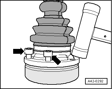
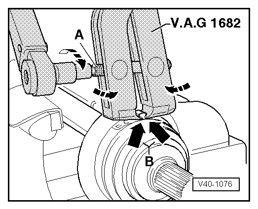
| 4 - | Hose clip |
| q | Renew |
| q | Tightening → Fig. or → Fig. |
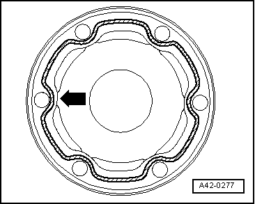
| 5 - | Boot for outer constant velocity joint |
| q | Without vent hole |
| q | Check for splits and chafing |
| 6 - | Hose clip |
| q | Renew |
| q | Tightening → Fig. or → Fig. |
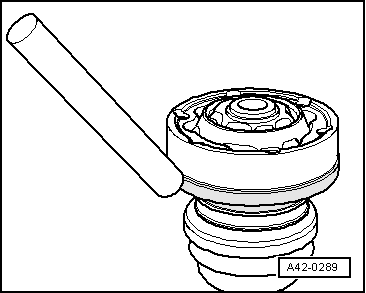
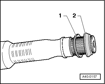
| 7 - | Dished spring |
| q | Installation position → Fig. |
| 8 - | Spacer ring (plastic) |
| q | Installation position → Fig. |
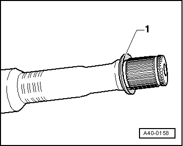
| 9 - | Circlip |
| q | Renew |
| q | Insert in groove on shaft |
| 10 - | Boot for inner constant velocity joint |
| q | Without vent hole |
| q | Check for splits and chafing |
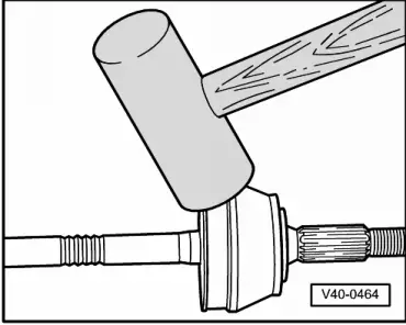
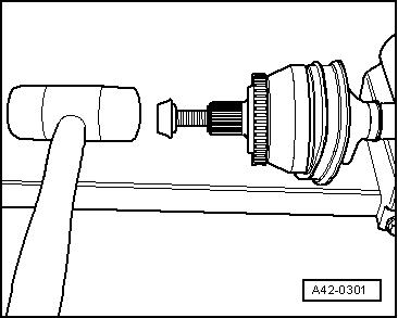
| q | Drive off constant velocity joint with a drift |
| q | Before fitting on constant velocity joint, coat sealing surface with D 454 300 A2 |
| 11 - | Hose clip |
| q | Renew |
| q | Tightening → Fig. or → Fig. |
| 12 - | Lock plate |
| 13 - | Multi-point socket head bolt |
| q | Always renew if removed |
| q | Initial tightening torque: 10 Nm in diagonal sequence |
| q | Tightening torque, M8: 40 Nm in diagonal sequence |
| q | Tightening torque, M10: 70 Nm in diagonal sequence |
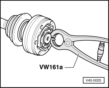
| 14 - | Circlip |
| q | Renew |
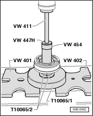
| q | Removing and installing with -VW 161 A- → Fig. |
| 15 - | Gasket |
| q | Adhesive surface on constant velocity joint must be free of oil and grease |
| 16 - | Inner constant velocity joint |
| q | Renew only as complete unit |
| q | Checking → Chapter |
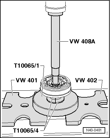
| q | Pressing off → Fig. |
| q | Greasing ⇒ see table → Anchor |
| q | Pressing on → Anchor |
| q | Grease splines on drive shaft lightly with grease used in joint when fitting joint onto drive shaft |
| 17 - | Dished spring |
| q | Installation position → Fig. |

| Special tools and workshop equipment required |
| t | Thrust plate -VW 401- |
| t | Thrust plate -VW 402- |
| t | Press tool -VW 408 A- |
| t | Press tool -VW 411- |
| t | Tube -VW 416 B- |
| t | Thrust plate -VW 447 H- |

| t | Circlip pliers -VW 161 A- |
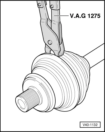
| t | Torque wrench -V.A.G 1331- |
| t | Torque wrench -V.A.G 1332- |
| t | Clamp tensioner -V.A.G 1682- |
| t | Assembly tool -T10065- |
|
|
|
|
|
|
|
|
|
|
|
|
|
|
|
|
|
|
|
Note
|
|
|
|
|
|
|
|
|
|