
A4 Cabriolet Mk2
|
 WARNING
|
 Note
Note| t | The seat occupied recognition system is only fitted on the front passenger's seat. |
| t | Modular wire routing has been used for the USA version from 06.06 onwards. |
| Perform the following operations before removing seat occupied recognition control unit -J706- → Item or service kit → Anchor: |
| – | Check type of front seats, vehicle model and whether or not modular wire routing has been employed, and perform repair work accordingly. |
| – | Check which of the two possible modular wire routing versions has been used, »Modular Light« or »Modular« → Chapter. |
| Refer to the following sections for further information on modular wire routing: |
| t | Exploded view of modular wire routing → Chapter |
| t | Modular wire routing versions → Chapter |
| t | Modular wire routing with corrugated tube at front seat → Chapter |
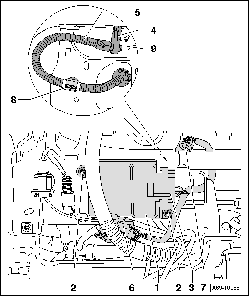
| 1 - | Seat occupied recognition control unit -J706- |
| Removing |
WARNING
|
| – | Disconnect battery earth strap → Electrical system; Rep. gr.27. |
| – | Remove front passenger seat → Chapter. |
| – | Attach seat repair stand -VAS 6136- to engine and gearbox support -VAS 6095-. |
| – | Attach front seat to seat repair stand -VAS 6136-. |
| – | Remove backrest → Chapter, for seat with electrical adjustment → Chapter. |
| – | Unplug connector -6-. |
| – | Remove bolts -2- (2x). |
| – | Detach seat cover → Chapter, → Chapter. |
| – | Unfasten guide clip -8-. |
 Caution
|
| – | Push pressure sensor for seat occupied recognition -G452--4- to side off retaining bracket -9-. |
| 2 - | Bolts |
| t | 2.5 Nm |
| 3 - | Connector at seat occupied recognition control unit -J706- |
| t | Do NOT unplug under any circumstances. |
| 4 - | Pressure sensor for seat occupied recognition -G452- |
| 5 - | Pressure hose |
| 6 - | Connector between service kit and seat wiring harness |
| q | Not fitted with »Modular« wire routing → Chapter |
| 7 - | Connector at pressure sensor for seat occupied recognition -G452- |
| t | Do NOT unplug under any circumstances. |
| 8 - | Guide clip |
| 9 - | Retaining bracket |
|
Note
Note
|
|
|
|
| All vehicles (continued) |
| 1 - | Seat occupied recognition control unit -J706- |
| Installing |
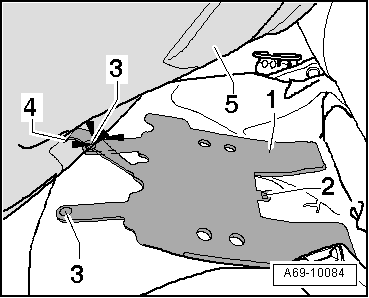
| – | Attach pressure sensor for seat occupied recognition -G452--4-. |
| – | Secure seat occupied recognition control unit -J706- with bolts -2- (2x, 2.5 Nm). |
| – | Plug in connector -6-. |
| – | Install padding for seat pan, making sure that all upholstery clips are engaged/installed in previous positions (before removal) → Chapter or → Chapter (for seats with electric seat adjustment). |
| Remaining installation is performed in reverse order of removal. Observe the following: |
| – | After fitting front passenger's seat in vehicle, carry out the following program under „Airbag“ in the Guided Fault Finding. |
| After installing a new service kit and after carrying out any repairs on the front passenger seat: |
| t | Basic setting for seat occupied recognition control unit -J706- |
| After fitting seat |
| – | Switch on ignition with battery disconnected. |
WARNING
|
| – | Connect battery → Rep. gr.27. |
Note| If the airbag warning lamp -K75- indicates a fault following installation, use the vehicle diagnostic, testing and information system -VAS 5051 A- to interrogate, erase and then re-interrogate the event memory. |
| 2 - | Bolts |
| t | 2.5 Nm |
| 3 - | Connector at seat occupied recognition control unit -J706- |
| t | Do NOT unplug under any circumstances. |
| 4 - | Pressure sensor for seat occupied recognition -G452- |
| 5 - | Pressure hose |
WARNING
|
| – | Secure pressure hose to guide clip -8- at marking provided. |
| 6 - | Connector between service kit and seat wiring harness |
| q | Not fitted with »Modular« wire routing → Chapter |
| 7 - | Connector at pressure sensor for seat occupied recognition -G452- |
| t | Do NOT unplug under any circumstances. |
| 8 - | Guide clip |
| 9 - | Retaining bracket |