
A4 Cabriolet Mk2
|
|
|
 WARNING
|
|
|
|
|
|
|
|
|
|
|
|
|
|
|
|
 Note
Note
|
|
|
|
|
|
|
|
|
|
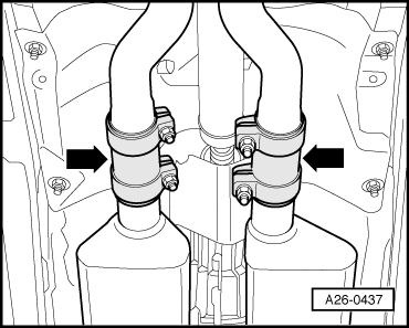
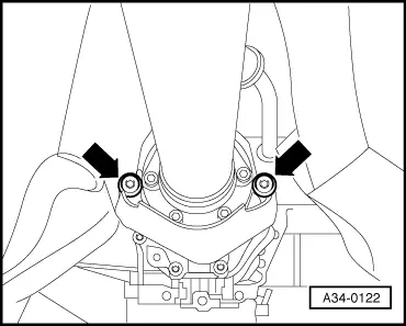
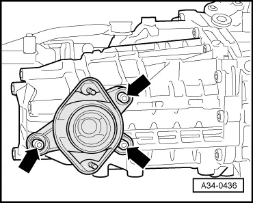
| Bolts -arrows- | 23 Nm |
|
|
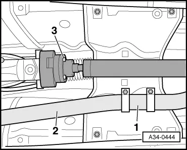
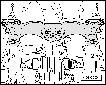
| Component | Nm | |||||
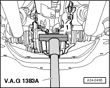
| -1- Tunnel cross member to gearbox mounting | 23 | |||||
| -2- Tunnel cross member to body 1) | 110 Nm + 90° 2) | |||||
| -3- Tunnel cross member to body 1) | M10 | 55 | ||||
| ||||||
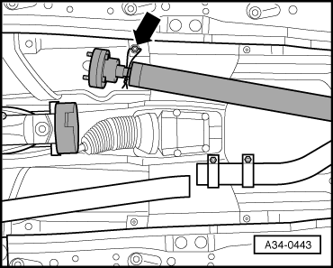
| Component | Nm | |||
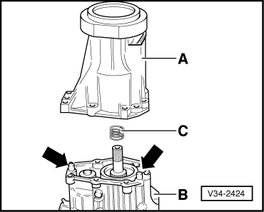
| Cover with centre differential to gearbox | 22 | |||
| Propshaft to manual gearbox 1) | 55 | |||
| Heat shield for propshaft to cover for centre differential | 25 | |||
| ||||