
A4 Cabriolet Mk2
 Note
Note
|
|
|
|
|
Note
|
|
 Caution
|
|
|
|
Note
|
|
|
|
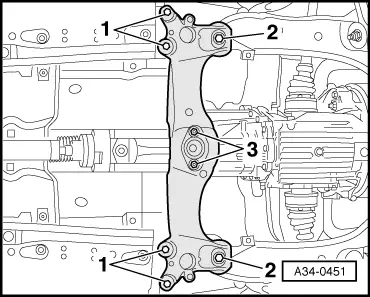
| Item | Bolt | Nm | ||||||
| 1 | M12 x 67 | 65 | ||||||
| 2 | M12 x 110 1) | 65 | ||||||
| 3 | M12 x 90 | 65 | ||||||
| 4 | M10 x 50 2) | 45 | ||||||
| 5 | M10 x 45 | 45 | ||||||
| 6 | M12 x 110 3) | 65 | ||||||
| A | Dowel sleeves for centralising | |||||||
| ||||||||
|
|
| Item | Bolt | Nm | ||||||
| 1 | M12 x 75 | 65 | ||||||
| 2 | M12 x 110 1) | 65 | ||||||
| 3 | M12 x 90 | 65 | ||||||
| 4 | M10 x 50 2) | 45 | ||||||
| 5 | M10 x 45 | 45 | ||||||
| 6 | M12 x 110 3) | 65 | ||||||
| A | Dowel sleeves for centralising | |||||||
| ||||||||
|
|
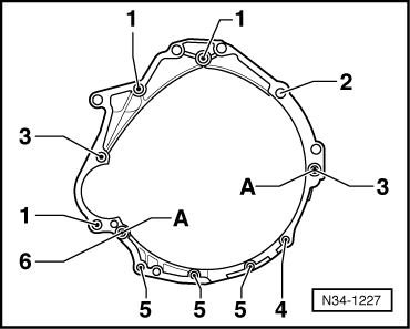
| Item | Bolt | Nm | ||
| 1, 10, 11 | M10x60 | 45 | ||
| 2 | M12x130 | 65 | ||
| 3 | M10x150 | 45 | ||
| 4 | M12x80 | 65 | ||
| 5, 6, 8 | M12x80 | 65 | ||
| 7 | M12x105 | 65 | ||
| 9 | M10x59 | 45 | ||
| A | Dowel sleeves for centralising | |||
| ||||
|
|
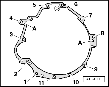
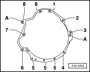
| Item | Bolt | Nm | ||
| 1, 3 | M12x80 | 65 | ||
| 2 | M12x90 | 65 | ||
| 4 | M10x50 | 45 | ||
| 5 | M10x45 | 45 | ||
| 6, 7 | M12x110 | 65 | ||
| 8 | M12x67 | 65 | ||
| A | Dowel sleeves for centralising | |||
| ||||
| Component | Nm | ||
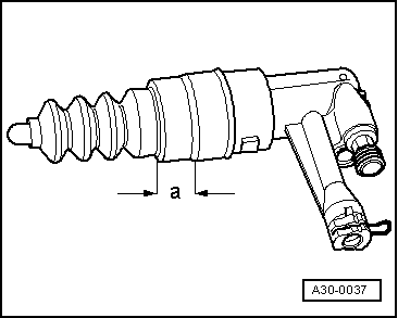
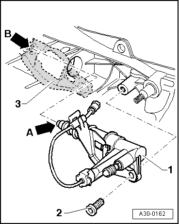
| Clutch slave cylinder to gearbox | 25 1) | ||
| Push rod to gearbox | 40 | ||
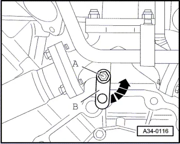
| Selector shaft lever to gearbox | 23 | ||
| Connecting rod for selector rod to gearbox | 23 | ||
| Engine speed sender -G28- to gearbox | 10 | ||
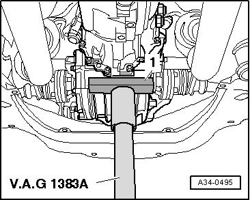
| Gearbox mounting with bracket to gearbox | 23 | ||
| Heat shield for drive shaft to gearbox | 23 | ||
| Heat shield for propshaft to Torsen differential cover | 25 | ||
| Bracket for noise insulation to subframe | 10 | ||
| Air duct to throttle valve housing | 10 | ||
| |||