
A4 Cabriolet Mk2
 Note
Note
|
|
Note
|
|
|
|
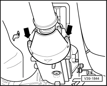
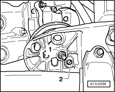
 Caution
|
|
|
|
|
|
|
|
|
|
|
|
|
|
|
|
|
|
|
|
|
|
|
|
|
|
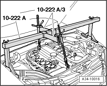
Note
|
|
|
|
|
|
|
|
|
|
Note
|
|
|
|
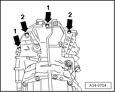
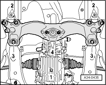
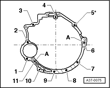
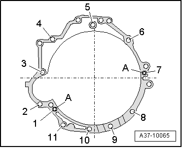
| Item | Bolt | Nm |
| 1 1) | M12 x 75 | 65 |
| 2 1) | M12 x 90 | 65 |
| 3 2) | M12 x 75 | 65 |
| 4, 6 | M12 x 90 | 65 |
| 5 2) | M12 x 110 | 65 |
| 7 3) | M10 x 50 | 45 |
| 8, 9, 10 | M10 x 45 | 45 |
| 11 4) | M12 x 110 | 65 |
| A | Dowel sleeves for centralising | |
| 1) Secures starter to gearbox 2) With bracket for wiring harness 3) Hammer head bolt with nut 4) With nut | ||
|
|
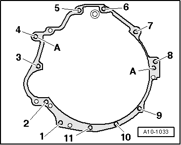
| Item | Bolt | Nm |
| 1 1) | M12 x 80 | 65 |
| 2 1) | M12 x 95 | 65 |
| 3 2) | M12 x 80 | 65 |
| 4, 6 | M12 x 95 | 65 |
| 5 2) | M12 x 110 | 65 |
| 7 3) | M10 x 50 | 45 |
| 8, 9, 10 | M10 x 45 | 45 |
| 11 4) | M12 x 110 | 65 |
| A | Dowel sleeves for centralising | |
| 1) Secures starter to gearbox 2) With bracket for wiring harness 3) Hammer head bolt with nut 4) With nut | ||
|
|
| Item | Bolt | Nm |
| 1 1) | M12 x 105 | 65 |
| 2 2) | M12 x 80 | 65 |
| 3 2) | M12 x 90 | 65 |
| 4 3) | M12 x 80 | 65 |
| 5, 7 | M12 x 95 | 65 |
| 6 3) | M12 x 105 | 65 |
| 8 4) | M10 x 50 | 45 |
| 9, 10, 11 | M10 x 45 | 45 |
| A | Dowel sleeves for centralising | |
| 1) With nut 2) Secures starter to gearbox 3) With bracket for wiring harness 4) Hammer head bolt with nut | ||
|
|
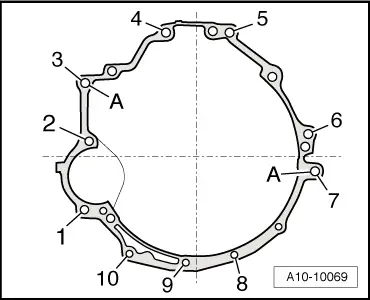
| Item | Bolt | Nm |
| 1, 10, 11 | M10 x 60 | 45 |
| 2 1) | M10 x 150 | 65 |
| 3 1) | M12 x 130 | 65 |
| 4 | M12 x 85 | 65 |
| 5, 6 | M12 x 90 | 65 |
| 7 | M10 x 100 | 45 |
| 8 | M12 x 95 | 65 |
| 9 2) | M10 x 60 | 45 |
| A | Dowel sleeves for centralising | |
| 1) Secures starter to gearbox 2) Hammer head bolt with nut | ||
|
|
| Item | Bolt | Nm |
| 1 1) | M12 x 140 | 65 |
| 2 1) | M12 x 155 | 65 |
| 3 | M12 x 110 | 65 |
| 4 | M12 x 115 | 65 |
| 5 | M12 x 110 | 65 |
| 6 | M12 x 125 | 65 |
| 7 2) | M10 x 160 | 65 |
| 8, 9, 10 | M10 x 80 | 45 |
| A | Dowel sleeves for centralising | |
| 1) Secures starter to gearbox 2) With nut | ||
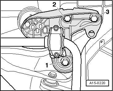
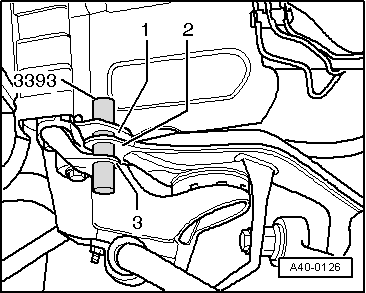
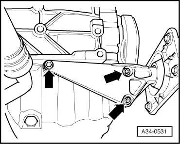
| Component | Nm | |
| Gearbox mounting to gearbox | 23 | |
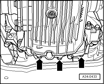
| Heat shields above drive shafts to gearbox | 23 | |
| Heat shield for propshaft to gearbox cover | 25 | |
| Engine mounting to engine support | 23 | |
| Torque reaction support to engine (Cabriolet only) | 30 + 90° 1) | |
| Bracket for noise insulation to subframe | 10 | |
| 1) Renew bolt | ||