audi Workshop Repair Guides

Audi Workshop Service and Repair Manuals

Installing gearbox on vehicles with 3.2 ltr. FSI engine > < Installing gearbox - vehicles with 2.0 ltr. TFSI engine
Removing gearbox on vehicles with 3.2 ltr. FSI engine
   
Removing gearbox on vehicles with 3.2 ltr. FSI engine
Special tools and workshop equipment required
t  Support bracket -10-222 A-
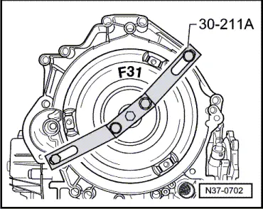
t  Support bridge -30-211 A-
t  Gearbox support -3282-
t  Adjustment plate -3282/48-
t  Pin -3282/50-
t  Engine and gearbox jack -V.A.G 1383 A-

   
t  Used oil collection and extraction unit -V.A.G 1782-
t  Wing compensation plate -T40045-
t  Adapter -T40058-
t  Bolt M10x20

Removing
  Note
t  General repair instructions → Chapter.
t  Rules for cleanliness when working on the automatic gearbox → Chapter.
t  All cable ties which are released or cut open during removal must be fitted in the same position when installing.
–  Shift selector lever to position “N”.
  Caution
Follow steps required when disconnecting battery → Electrical system; Rep. Gr.27.
   
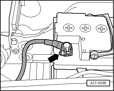
–  With ignition switched off, disconnect earth wire -arrow- at battery.
–  Remove front exhaust pipe with catalytic converter (left and right) → Rep. Gr.26.
  Note
t  After removal of the front exhaust pipes the subframe is detached at the rear and the gearbox support (left-side) is removed.
  A27-0098
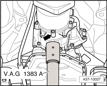
t  The gearbox is supported centrally at the connection on the housing -arrow- with engine and gearbox jack -V.A.G 1383 A-.
–  Use engine and gearbox jack -V.A.G 1383 A- to lift gearbox up slightly.
  A37-10027
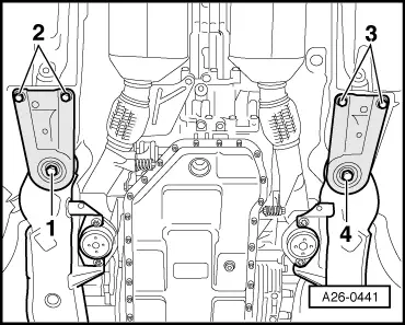
–  Fit bolts -1- and -4- hand-tight.
  Note
-Item 2- and -item 3- can be disregarded.
–  Lower gearbox and take out engine and gearbox jack -V.A.G 1383 A- from under vehicle.
  A26-0441
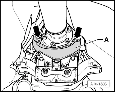
–  Unbolt heat shield -A- for propshaft -arrows-.
–  Unscrew bolts at gearbox/propshaft flange.
–  Slide propshaft together towards rear final drive. The constant velocity joints can be moved axially.
–  Rest propshaft on exhaust system (right-side).
  Note
  A10-1603
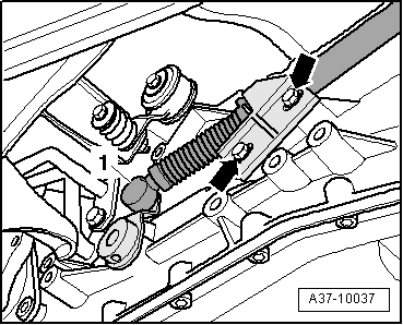
Mark installation position of support bracket for selector lever cable with a felt-tip pen.
–  Pry ball socket -1- of selector lever cable off selector shaft lever.
–  Unscrew support bracket from gearbox -arrows-.
  Note
Do not bend or kink the selector lever cable.
  A37-10037
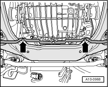
–  Unbolt bracket for noise insulation -arrows-.
  Note
  A10-0968
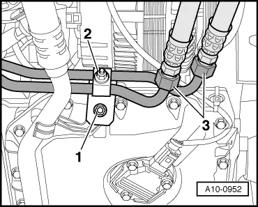
Observe rules for cleanliness when working on automatic gearbox → Chapter.
–  Place used oil collection and extraction unit -V.A.G 1782- below engine.
–  Unscrew union nuts -3- and disconnect ATF pipes.
–  Unbolt bracket -2- securing ATF pipes.
  Note
-Item 1- can be disregarded.
  A10-0952
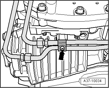
–  Unbolt bracket -arrow- for ATF pipes at bottom section of gearbox.
  Note
  A37-10034
Place a cloth below the ATF pipe to catch escaping ATF.
–  Unscrew bolt -arrow-.
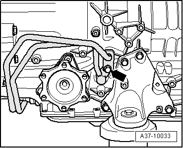
–  Pull ATF pipes out of gearbox.
  A37-10033
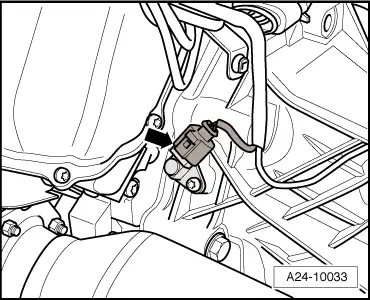
–  Unplug electrical connector -arrow- for engine speed sender -G28-.
  A24-10033
–  Disconnect electrical connector at gearbox by turning fastener cap anti-clockwise -arrow-.
  WARNING
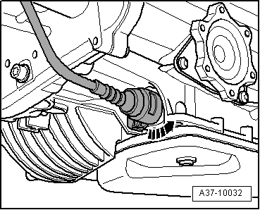
Check once again to make sure that the rear subframe mountings are secured hand-tight.
  A37-10032
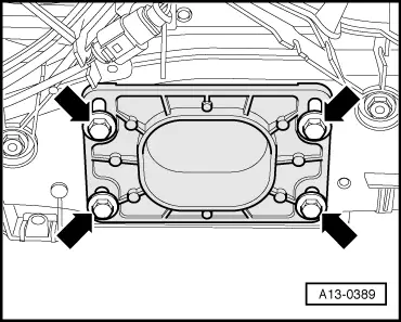
–  Unscrew bolts -arrows- two turns at stop for torque reaction support.
  A13-0389
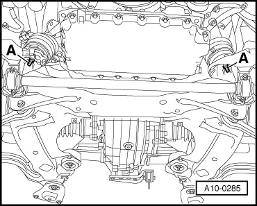
–  Unscrew nuts -A- below left and right engine mountings until nuts are flush with bottom end of studs.
  A10-0285
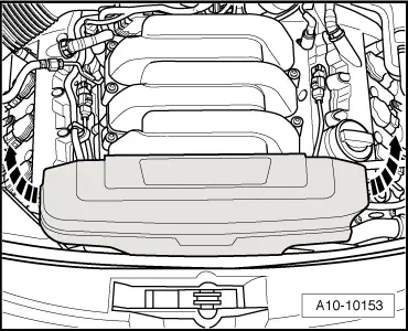
–  Pull off front engine cover -arrows-.
  A10-10153
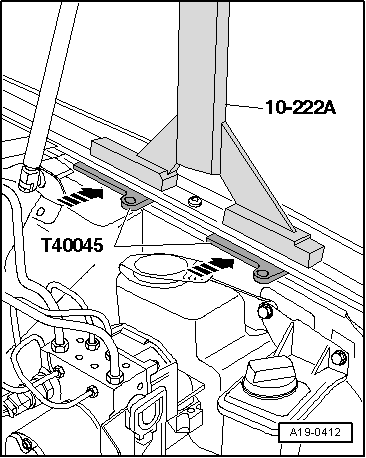
–  Detach rubber seal from edges of wing mounting flanges.
–  To avoid damaging edges of wing panels with support bracket -10-222 A-, insert wing compensation plates -T40045- on both sides between the wing mounting flange and the body panel underneath.
  A19-0412
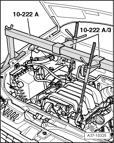
–  Set up support bracket -10-222 A- with adapters -10-222 A/3- on wing mounting flanges.
–  Engage spindles on engine lifting eyes as illustrated.
–  Take up weight of engine with spindles until bottom engine/gearbox securing bolts are accessible.
  A37-10325
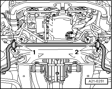
–  Unbolt anti-roll bar mountings on both sides -1- and -2-.
–  Swivel anti-roll bar downwards.
  A21-0251
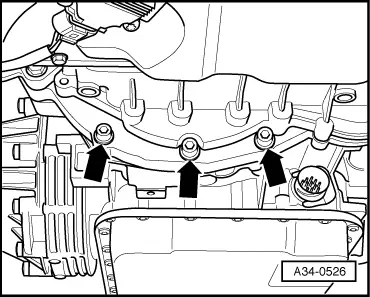
–  Unscrew bottom engine/gearbox securing bolts -arrows-.
  A34-0526
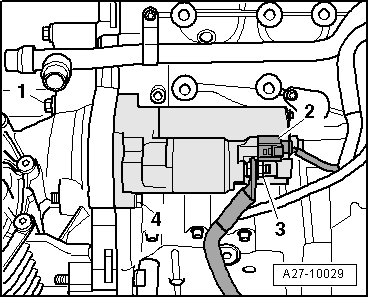
–  Disconnect wires -2- and -3- at starter.
–  Unscrew bolts -1- and -4- and remove starter.
–  Guide out starter towards the rear through wheel housing on right side of vehicle.
  A27-10029
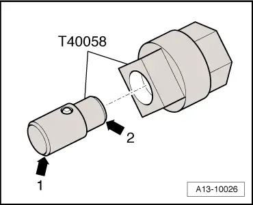
–  Insert guide pin of adapter -T40058- so that the large diameter -arrow 1- faces engine. The smaller diameter -arrow 2- faces adapter.
  A13-10026
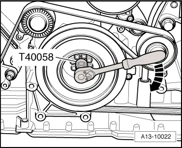
–  Counter-hold crankshaft using adapter -T40058- to slacken torque converter bolts.
  Note
-Arrow- can be disregarded.
  A13-10022
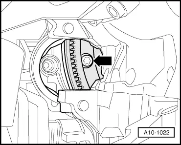
–  Unscrew the 3 torque converter bolts -arrows- through the opening for the removed starter (turning the crankshaft 1/3 turn each time).
  A10-1022
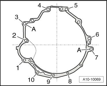
–  Remove engine/gearbox securing bolts -4 ... 6-.
  Note
Bolts -3- and -7- remain screwed in hand-tight.
  A10-10069
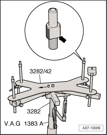
–  Set up gearbox support -3282- on engine and gearbox jack -V.A.G 1383 A-.
–  Place adjustment plate -3282/48- on gearbox support -3282- as shown in illustration.
–  Align arms of gearbox support according to holes in adjustment plate.
–  Attach support elements as illustrated on adjustment plate.
–  Note: The pin -3282/50- has to be screwed in at rear right.
–  Place engine and gearbox jack -V.A.G 1383 A- with gearbox support -3282- underneath gearbox.
  Note
The arrow symbol on the adjustment plate points in the direction of travel.
–  Align adjustment plate parallel with gearbox.
  A37-10009
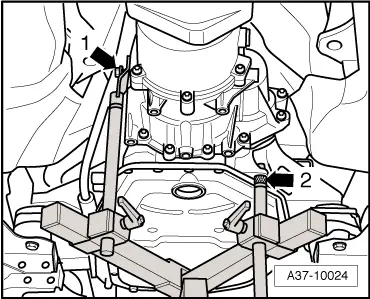
–  Bolt support to rear left tapped hole on gearbox -1- using one bolt M10x20.
–  Insert flattened bolt -3282/50- into mounting hole at rear right of gearbox housing -arrow 2-.
  Caution
t  The flattened side of the bolt must face towards the gearbox oil pan to prevent the oil pan from being bent or damaged.
t  Renew the gearbox oil pan if damaged.
  A37-10024
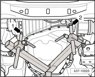
–  Insert bolt into mounting hole at front left of gearbox housing -arrow 2-.
–  Insert pin into recess in housing at front right of differential housing -arrow 1-.
–  Raise gearbox slightly.
  A37-10023
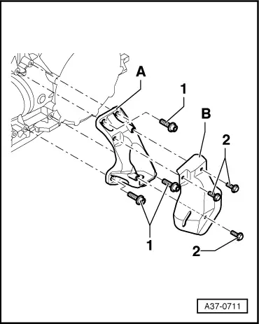
–  Remove bolts -2- at gearbox support (right-side) and detach heat shield -B-.
–  Unscrew bolts -1-.
–  Detach gearbox support -A- together with gearbox mounting from gearbox.
  A37-0711
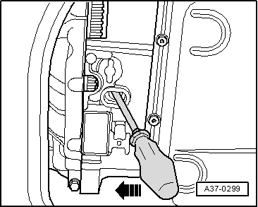
–  Remove the last engine/gearbox securing bolts.
–  Push gearbox off engine and at the same time lever torque converter off drive plate using a screwdriver.
–  Carefully lower gearbox using engine and gearbox jack -V.A.G 1383 A-.
  Note
When lowering gearbox, make sure there is sufficient clearance from drive shafts.
  A37-0299
–  Secure torque converter in gearbox with support bridge -30-211 A- to prevent it dropping out.
  N37-0702

Installing gearbox on vehicles with 3.2 ltr. FSI engine > < Installing gearbox - vehicles with 2.0 ltr. TFSI engine