
A4 Cabriolet Mk2
 Note
Note
|
Note
|
|
|
|
Note
|
|
|
|
 Caution
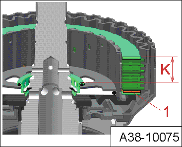
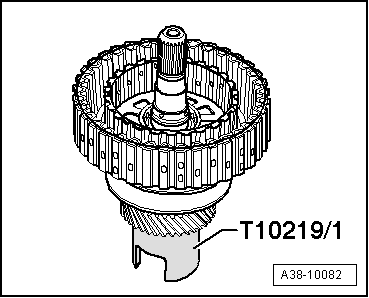
Note |
|
|
|
|
|
|
|
|
|
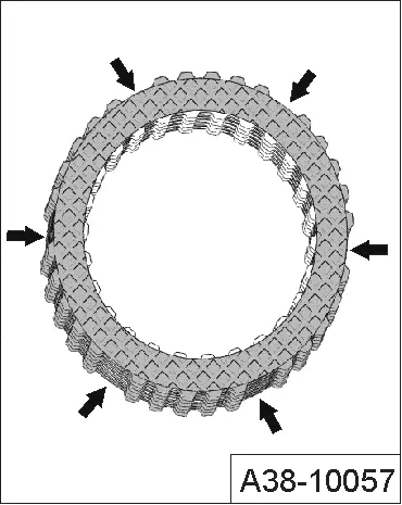
Note
|
|
|
|
|
|
|
|
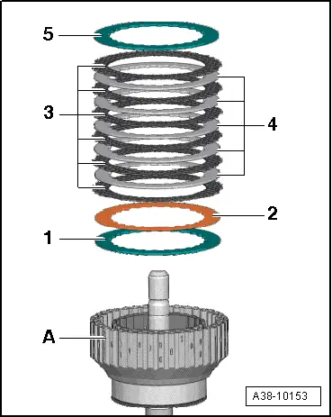
| Mean value of pressure plate measurements “M D” (value 1 + value 2 + value 3) : 3 | |
| – | Mean value of clutch measurements “MK” (value 1 + value 2 + value 3 + value 4) : 4 |
| = | Clearance |
|
| Available shims [thickness in mm] | ||
| 1,90 | 2,15 | 2,65 |
| 2,90 | 3,15 | |
Note
|
|
|