
A4 Cabriolet Mk2
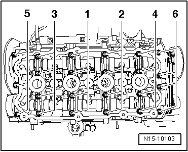
| Valve gear - exploded view |

| 1 - | 50 Nm + 180° |
| q | Renew |
| 2 - | Camshaft sprocket |
| 3 - | Oil seal |
| q | Renewing → Chapter |
| 4 - | Cylinder head |
| 5 - | Valve guide |
| q | Checking → Chapter |
| 6 - | Valve stem oil seal |
| q | Renewing with cylinder head installed → Chapter |
| q | Renewing with cylinder head removed → Chapter |
| 7 - | Valve spring |
| 8 - | Upper valve spring plate |
| 9 - | Cotters |
| 10 - | Hydraulic valve clearance compensation element |
| q | Do not interchange |
| q | Lubricate contact surface |
| 11 - | Parallel key |
| q | Check for firm attachment |
| 12 - | Exhaust camshaft |
| q | Check radial clearance with Plastigage (rocker fingers not installed). Wear limit: 0.1 mm |
| q | Runout: max. 0.035 mm |
| 13 - | Retaining frame |
| q | With integrated camshaft bearings |
| q | Clean sealing surface; machining not permitted |
| q | Remove old sealant residues |
| 14 - | Bolt |
| q | Renew |
| q | Tightening sequence → Fig. |
| 15 - | Camshaft adjuster |
| 16 - | 20 Nm + turn 45° further |
| q | Renew |
| 17 - | Inlet camshaft |
| q | Check radial clearance with Plastigage (rocker fingers not installed). Wear limit: 0.1 mm |
| q | Runout: max. 0.035 mm |
| 18 - | Chain tensioner |
| q | Remove → Chapter Removing and installing camshaft adjuster |
| q | Before removing, lock in place using locking pin -T10115- |
| 19 - | Drive chain |
| q | Check for wear |
| 20 - | 10 Nm |
| 21 - | 10 Nm |
| 22 - | Phase sensor |
| 23 - | Exhaust valve |
| q | Do not machine, only grinding-in is permitted |
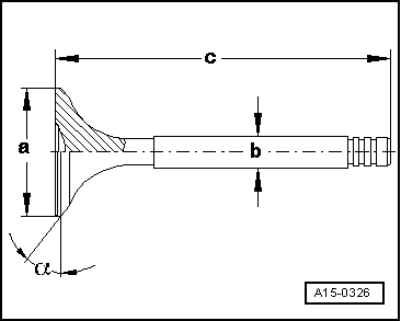
| q | Valve dimensions → Fig. |
| q | Checking valve guides → Chapter |
| 24 - | Inlet valve |
| q | Do not machine, only grinding-in is permitted |
| q | Valve dimensions → Fig. |
| q | Checking valve guides → Chapter |
| 25 - | Sealing cap |
| q | Renew |
| q | Removing sealing cap with retaining frame installed: pierce on one side with an awl and pry out |
| q | Installing: press in 1 ... 2 mm deep without sealant using thrust piece -3334- |
|
|
|
 Note
Note
|
|
| Dimension | Inlet valve | Exhaust valve | |
| Ø a | mm | 33.85 ± 0.10 | 28.0 ± 0.1 |
| Ø b | mm | 5.98 ± 0.01 | 5.96 ± 0.01 |
| c | mm | 104.0 ± 0.2 | 101.9 ± 0.2 |
| α | ∠° | 45 | 45 |