| –
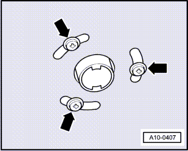
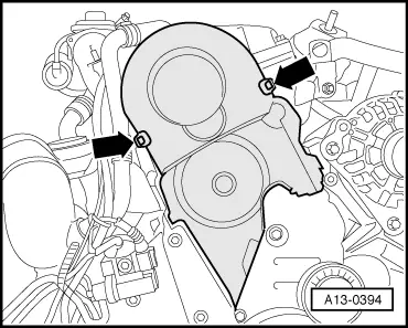
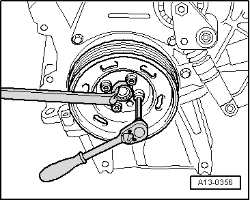
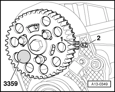
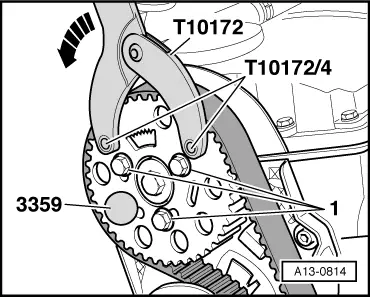
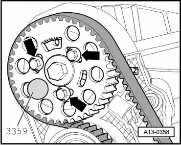
| Tighten securing bolts for camshaft sprocket -arrows- to 25 Nm. |
| –
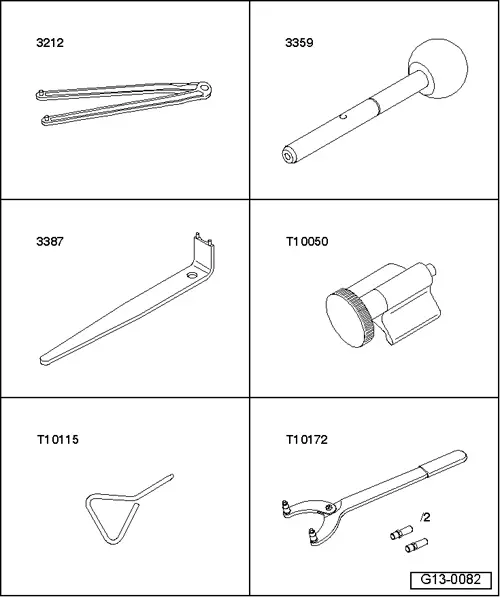
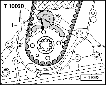
| Remove locking pin -3359- and crankshaft stop -T10050-. |

Caution | The engine must only be turned at the crankshaft, in the direction of normal engine rotation (clockwise). |
|
| –
| Turn crankshaft two rotations in normal direction of rotation until crankshaft is at TDC again. |
| –
| Check valve timing once again → Anchor. |
| Installation is carried out in the reverse order; note the following: |

Note | t
| Renew seals and gaskets. |
| t
| To ensure that the charge air hoses can be properly secured at their connections, spray rust remover onto the worm thread of used hose clips before installing. |
| –
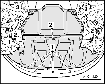
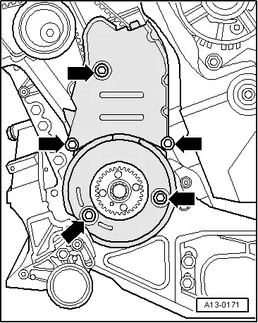
| Install toothed belt cover (bottom and centre). |
| –
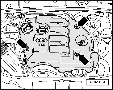
| Fit toothed belt cover (top section). |
| –
| Install vibration damper: vehicles up to 05.2003 → Anchor, vehicles from 06.2003 onwards → Anchor. |
| –
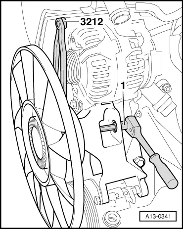
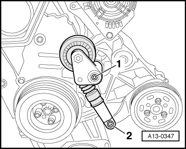
| Install poly V-belt: vehicles up to 05.2003 → Anchor, vehicles from 06.2003 onwards → Anchor. |
|
|
|