
A4 Cabriolet Mk2
| Removing and installing sump (top section) |

| Special tools and workshop equipment required |
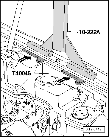
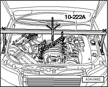
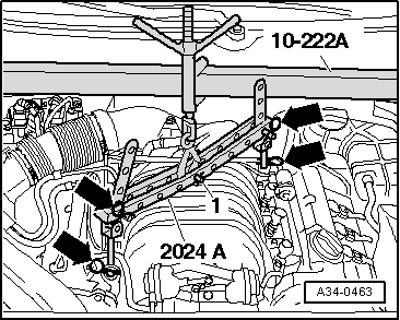
| t | Support bracket -10-222 A- |
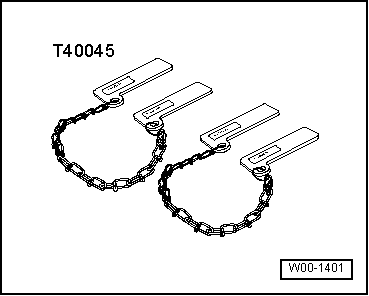
| t | Lifting tackle -2024 A- |
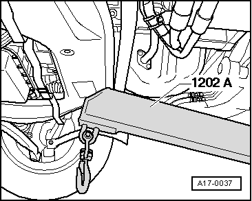
| t | Workshop hoist -VAS 6100- or -V.A.G 1202 A- |
| t | Drip tray for workshop hoist -VAS 6208- or -V.A.G 1306- |
|
|
 Note
Note
|
|
 Caution
|
|
|
|
|
|
|
|
 WARNING
|
|
|
|
|
|
|
|
|
|
Note |
|
|
|
|
|
|
|
|
|
Note
|
|
|
|
|
|
|
|
|
|
|
|
Note
|
|
|
|
|
|
|
|
|
|
Note
|
|
|
|
Note
|
|
|
|
|
|
|
|
| Component | Nm | |
| Balance shaft housing to sump (top section) | 22 | |
| Sump (top section) to: | Cylinder block and sealing flanges | 16 |
| Gearbox | 45 → Note | |
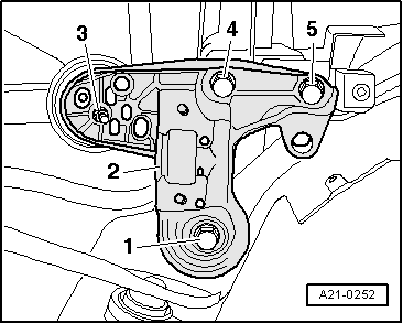
| Console for engine mounting to longitudinal member | 75 | |
| Engine mounting to console for engine mounting | 23 | |
| Bracket for A/C compressor to: | Sump (top section) | 22 |
| Bracket for power steering pump and oil cooler | 22 | |
| Torque reaction support to top section of sump | 40 | |
| Stop for torque reaction support | 28 | |
|