audi Workshop Repair Guides

Audi Workshop Service and Repair Manuals

Servicing valve gear > < Removing and installing intake manifold
Checking compression
   
Checking compression
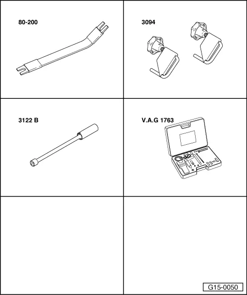
Special tools and workshop equipment required
t  Removal lever -80-200-
t  Hose clamps for hoses up to 25 mm Ø -3094-
t  Spark plug socket and extension -3122 B-
t  Compression tester -V.A.G 1763-

Test conditions
l  Engine oil temperature at least 30 °C.
l  Battery voltage at least 12.5 V
   
Test sequence
–  Remove engine cover panel -arrows-.
  A10-0113
–  Remove cover -1- on left side of engine compartment.
  A10-1031
–  Clamp off coolant hose -2- using hose clamp -3094- and detach coolant hose from coolant expansion tank.
–  Unbolt coolant expansion tank -arrow-.
–  Disconnect electrical wiring for coolant shortage indicator switch -F66- at coolant expansion tank (bottom).
–  Tie coolant expansion tank to one side; coolant hoses -1- and -3- remain connected.
  A10-0989
–  Remove cover -1- at right of engine compartment.
  A10-1030
–  Remove bolts -arrows-.
–  Disengage activated charcoal filter solenoid valve 1 -N80--item 1- at air duct.
–  Remove air duct -2-.
  A10-0900
–  Pry off retaining clips -2- for wiring harness at air cleaner housing (use removal lever -80-200-).
–  Unplug electrical connector -1- at air mass meter -G70-.
–  Remove air cleaner housing -arrows-.
  A15-0787
–  Remove covers for cylinder head cover (left and right) -arrows-.
  A15-0786
–  Pull off all six spark plug connectors -arrows-.
–  Remove spark plugs with spark plug socket -3122 B-.
  A02-0016
–  Detach electrical 5-pin connector -1- from ignition coil output stage -2-.
–  Unplug electrical connectors at all injectors.
–  Test the compression pressure with the compression tester -V.A.G 1763-.
  Note
Using the compression tester → operating instructions.
–  Have a 2nd mechanic press down the accelerator pedal completely and simultaneously operate the starter until the pressure no longer increases on the tester display.
Compression pressure:
  N28-0117
New
pressure in bar
Wear limit
bar
Permissible difference between cylinders
bar
9.0 … 14.07.53.0 (maximum)

Installation is carried out in the reverse order; note the following:
–  Fill cooling system → Anchor.
–  Interrogate and erase the fault memory for engine control unit after testing compression pressure, as faults are stored when the connectors are unplugged → Vehicle diagnosis, testing and information system VAS 5051.
Tightening torque
   
ComponentNm
Spark plugs in cylinder head30


Servicing valve gear > < Removing and installing intake manifold