
A4 Cabriolet Mk2
 Note
Note
|
|
|
|
|
|
|
|
|
|
|
 WARNING
|
|
|
|
|
|
|
|
|
|
Note
|
|
|
|
Note
Note
|
|
|
|
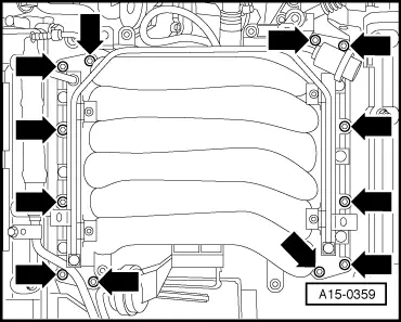
| Component | Nm |
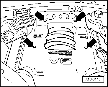
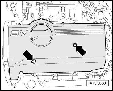
| Intake manifold to cylinder head | 10 |
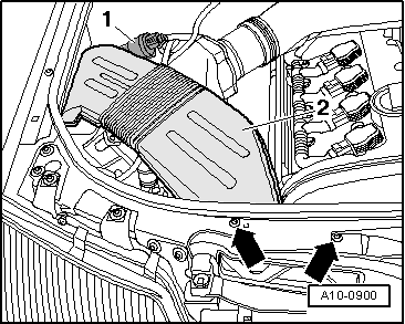
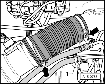
| Air duct to intake manifold | 10 |
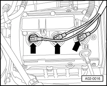
| Retaining plate for solenoid valves to intake manifold / air duct | 10 |
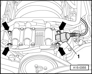
| Ignition coils to power steering pump | 10 |
| Fuel supply line to fuel rail | 25 |