audi Workshop Repair Guides

Audi Workshop Service and Repair Manuals

Removing and installing intermediate flange on vehicles with 3.0 ltr. engine > < Removing and installing turbocharger on vehicles with 3.0 ltr. engine
Removing and installing turbocharger 1 control unitJ724 - vehicles with 3.0 ltr. engine
Removing and installing turbocharger 1 control unit -J724- - vehicles with 3.0 ltr. engine
Special tools and workshop equipment required
t  Tester -VAS 6395/1-
t  Connection lead -VAS 6395/4-2-
t  Open-end spanner, 10 mm (90 mm long) -VAS 6395/4-3-
   
Removing
Proceed as follows:
–  Carefully pull engine cover panel off four retaining pins one after the other -arrows-.
  A10-10171
–  Remove bolts -arrows- and detach heat shield for turbocharger.
  Note
The bottom bolt -right arrow- does not have to be completely removed.
  A26-10011
–  Connect tester -VAS 6395/1- with connecting wire -VAS 6395/2- to positive battery terminal -arrow- and negative battery terminal.
  A27-0098
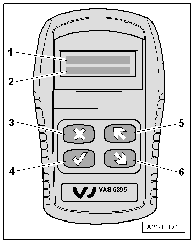
Checking software version of tester -VAS 6395/1-:
  Caution
Risk of damage to turbocharger 1 control unit -J724-.
Before continuing, check whether the correct software version is loaded in the tester -VAS 6395/1-. To do so, proceed as follows:
Display on -VAS 6395/1- (2 seconds after connecting to power supply) if correct software version is loaded:
1 - >TEST
2 - LEARN
  Note
t  If the following appears on the display, an incorrect software version has been loaded:
t  1. START
t  2. NEXT [>]
t  If this is the case, download the correct software version from the „Audi ServiceNet“ under „Workshop Equipment“.
  A21-10171
Continuation of procedure:
–  Unplug electrical connector for turbocharger 1 control unit -J724-.
–  Connect connection lead -VAS 6395/4-2- to turbocharger 1 control unit -J724- and to tester -VAS 6395/1-.
  A21-10256
Display on -VAS 6395/1-:
1 - >TEST
2 - LEARN
–  To continue, press v button -item 4-.
  A21-10171
Display on -VAS 6395/1-:
1 - CHECK
2 - S: XX %    I: XX %
l  The tester -VAS 6395/1- runs through the adjustment range of the turbocharger 1 control unit -J724- and checks the feedback of the positions.
  A21-10171
Display on -VAS 6395/1- if turbocharger 1 control unit -J724- is OK:
1 - ACTUATOR OK
l  The test is completed.
–  Unplug electrical connectors for tester -VAS 6395/1-.
Assemble in reverse order.
  A21-10171
Display on -VAS 6395/1- if turbocharger 1 control unit -J724- is not OK:
1 - PROBLEM
l  Renew turbocharger 1 control unit -J724-.
  A21-10171
–  To do so, proceed as follows:
–  To continue, press v button -item 4-.
Display on -VAS 6395/1-:
1 - >TEST
2 - LEARN
–  Press button -item 6-.
  A21-10171
Display on -VAS 6395/1-:
1 - TEST
2 - >LEARN
–  To continue, press v button -item 4-.
  A21-10171
Display on -VAS 6395/1-:
1 - STEP 1
–  By pressing buttons -item 5- and -item 6-, adjust turbocharger 1 control unit -J724- so that coupling rod can be accessed easily for removal.
  A21-10171
–  Unclip coupling rod -arrows- and dispose of it.
  A21-10254
–  To continue, press v button -item 4-.
Display on -VAS 6395/1-:
1 - STEP 2
  A21-10171
–  Disconnect connection lead -VAS 6395/4-2- from turbocharger 1 control unit -J724-.
  Caution
Power supply for tester -VAS 6395/1- must remain connected.
  A21-10256
–  Unclip retaining clip -1- for electrical wire.
–  Remove bolts -arrows-; use open-end spanner, 10 mm (90 mm long) -VAS 6395/4-3- for bolts at centre and bottom.
–  Remove old turbocharger 1 control unit -J724- and dispose of it.
–  Install new turbocharger 1 control unit -J724- in reverse order of removal, tighten bolts -arrows- only hand-tight.
l  Turbocharger 1 control unit -J724- must rest on retaining plate so there is no play; it must still be possible to move control unit by hand.
  A21-10255
–  Clip on new coupling rod -arrows-.
  A21-10254
–  Connect connection lead -VAS 6395/4-2- to turbocharger 1 control unit -J724-.
  A21-10256
–  To continue, press v button -item 4-.
Display on -VAS 6395/1-:
1 - STEP 3
  A21-10171
–  Press turbocharger 1 control unit -J724- downwards and towards rear using moderate pressure -arrow A-, at the same time tighten bolts -arrows B- to 10 Nm using open-end spanner, 10 mm (90 mm long) -VAS 6395/4-3- for centre and bottom bolts.
  A21-10257
–  To continue, press v button -item 4-.
Display on -VAS 6395/1-:
1 - WARNING
2 - LEARNING
  Caution
t  Now check correct installation of turbocharger 1 control unit -J724-; from the next step of the programme onwards (confirmed by the v button -item 4-) the turbocharger 1 control unit -J724- learns the limit positions of the adjustment travel once only. If the limit positions are not stored correctly due to an incorrect installation position, the learning procedure of turbocharger 1 control unit -J724- cannot be repeated and the control unit must be renewed.
t  If you are not certain that the installation position is correct, you can terminate the procedure by pressing the x button -item 3- and the start the procedure again.
  A21-10171
–  To confirm that the new turbocharger 1 control unit -J724- has been correctly installed, press v button -item 4-.
Display on -VAS 6395/1-:
1 - TEST 1
2 - S: 80.0 %    I: XX %
l  Specification: I = 80 %, successful learning is confirmed by the display „LEARNING“ in display zone -1-.
  A21-10171
–  At the same time, check position of adjustment lever at turbocharger 1 control unit -J724-:
l  The edge of adjustment lever -2- must be within marking -1-.
  A21-10258
–  To continue, press v button -item 4-.
Display on -VAS 6395/1-:
1 - TEST 2
2 - S: 16.0 %    I: XX %
l  Specification: I = 16 %, successful learning is confirmed by the display „LEARNING“ in display zone -1-.
  A21-10171
–  At the same time, check position of adjustment lever at turbocharger 1 control unit -J724-:
l  The edge of adjustment lever -1- must be within marking -2-.
  A21-10259
–  To continue, press v button -item 4-.
Display on -VAS 6395/1-:
1 - TEST 3
2 - S: 55.0 %    I: XX %
l  Check of centre position is now performed.
  A21-10171
–  To continue, press v button -item 4-.
Display on -VAS 6395/1-:
1 - OK
–  To confirm, press v button -item 4-.
l  Adjustment is completed.
–  Unplug electrical connectors for tester -VAS 6395/1-.
Assemble in reverse order.
  A21-10171

Removing and installing intermediate flange on vehicles with 3.0 ltr. engine > < Removing and installing turbocharger on vehicles with 3.0 ltr. engine