audi Workshop Repair Guides

Audi Workshop Service and Repair Manuals

Removing and installing exhaust gas temperature sender 2 for bank 1G448 > < Exhaust gas temperature control
Removing and installing exhaust gas temperature sender 1G235 - vehicles with 3.0 ltr. engine
Removing and installing exhaust gas temperature sender 1 -G235- - vehicles with 3.0 ltr. engine
   
Removing
  Note
All cable ties which are released or cut open when removing must be fitted in the same position when installing.
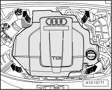
–  Carefully pull engine cover panel off four retaining pins one after the other -arrows-.
  A10-10171
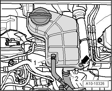
–  Unbolt coolant expansion tank -arrow-.
–  Detach electrical connector at coolant shortage indicator switch -F66- on coolant expansion tank (bottom).
–  Lay aside coolant expansion tank with coolant hoses -1- and -2- connected.
  A10-10326
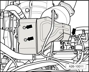
–  Remove heat shield for turbocharger -arrows-.
  A26-10011
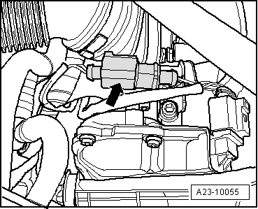
–  Unplug electrical connector -arrow- for exhaust gas temperature sender 1 -G235- and move wiring clear.
  A23-10055
–  Unscrew exhaust gas temperature sender 1 -G235--arrow-.
  Note
Shown from rear with engine removed for illustration purposes.
Installing
Installation is carried out in the reverse order; note the following:
  Note
Fit all cable ties in the original positions when installing.
Tightening torque
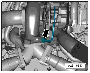
  A26-10333
ComponentNm
Exhaust gas temperature sender 1 -G235- to turbocharger45 1)
l  1) Grease thread with high-temperature paste; refer to → Electronic parts catalogue for high-temperature paste


Removing and installing exhaust gas temperature sender 2 for bank 1G448 > < Exhaust gas temperature control