
A4 Cabriolet Mk2
 |
|
|
 |
|
|
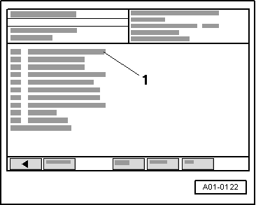
→ Readout on VAS 5051:
|
 |
|
|
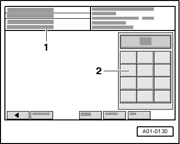
→ Readout on VAS 5051:
|
 |
|
|
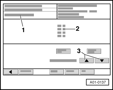
→ Readout on VAS 5051:
|
 |
|
→ Readout on VAS 5051:
|
 |
|
|
→ Readout on VAS 5051:
|
 |
|
|
→ Readout on VAS 5051:
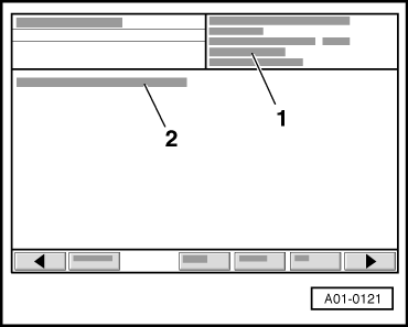
Watch the readout in display zone 3. When the engine is idling, a value of approx. 39 bar is shown in display zone 3. The readout shows the current pressure (actual pressure) in the fuel rail which is being generated by the high-pressure pump.
The readout in display zone 3 decreases very quickly because the mechanical high-pressure pump is no longer being supplied with fuel from the fuel tank by the electric fuel pump.
Note: The readout must not fall below 6 bar, otherwise the engine will stall (this could damage the catalytic converter). The fuel rail is still full of fuel; the fuel is, however, no longer under high pressure. Components or lines can now be opened. A clean cloth must be wrapped around the joints. Any discharged fuel must be collected.
|