| –
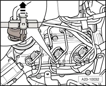
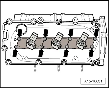
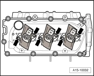
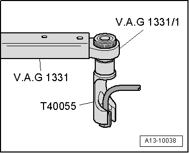
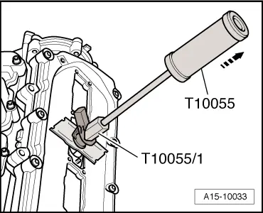
| Pull out injectors using puller -T10055- with adapter -T10055/1-. |
| –
| After removal, lay injectors on a clean cloth. |
| Important instructions for installing injectors: |
| l
| When removing and installing, always renew the following components and seals/O-rings: „copper seal“, „O-ring for injector bore“, „O-ring for injector return connection“. |
| l
| The following components and seals/O-rings must always be renewed when an injector is renewed: „clamping piece“, „copper seal“, „O-ring for injector bore“, „O-ring for injector return connection“ |
| l
| Used injectors and high-pressure pipes may only be re-installed on the same cylinders. |
| l
| Make sure that the injectors and the surrounding areas are clean before installing. |
| l
| The injectors must be completely undamaged. |
| l
| Lubricate all O-rings with engine oil or assembly oil before installing. |

Note | t
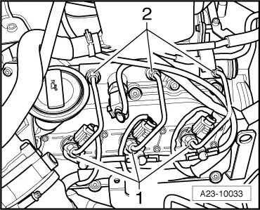
| Note identification marks for cylinder allocation when re-installing high-pressure pipes. |
| t
| The high-pressure pipes can be re-used after performing the following checks: |
| t
| Check taper seats of high-pressure pipes for deformation and cracks. |
| t
| The bore of the pipe must not be distorted, restricted or otherwise damaged. |
| t
| Corroded pipes must not be used again. |
| If a used injector is being re-installed: |
| –
| Spray tip of injector nozzle with rust-releasing spray. Wait approx. 5 minutes and wipe off soot particles and oil with a cloth. |
| –
| If an injector is very dirty, the tip of the nozzle should also be cleaned with a soft brass wire brush to make it easier to remove the copper seal. Do not apply the wire brush to the bores in the nozzle. |
| –
| To remove the old copper seal from the injector, clamp the seal carefully in a vice so that it is just held between the jaws without turning. Then carefully pull and twist the injector out of the copper seal by hand. |
| –
| Clean off deposits under the copper seal using a suitable scraper. |
| –
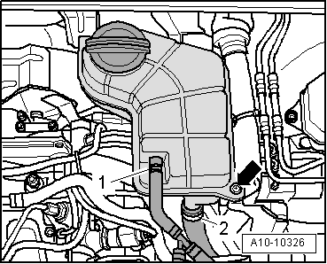
| Renew O-rings -2- at all return line connections. |
Note | Lubricate all seals with engine oil or assembly oil before installing. |
| –
| To remove carbon deposits from the injector sealing surface, clean the injector seat in the cylinder head with a cloth soaked in engine oil or rust solvent. Take care not to damage the sealing surface. |
Note | t
| Note identification marks for cylinder allocation when re-installing high-pressure pipes. |
| t
| The high-pressure pipes can be re-used after performing the following checks: |
| t
| Check taper seats of high-pressure pipes for deformation and cracks. |
| t
| The bore of the pipe must not be distorted, restricted or otherwise damaged. |
| t
| Corroded pipes must not be used again. |
| t
| Lubricate threads of union nuts with fuel. |
| –
| Hand-tighten union nuts on high-pressure pipes. Make sure that connections are not under tension. |
|
|
|


 Caution