audi Workshop Repair Guides

Audi Workshop Service and Repair Manuals

Ignition system, glow plug system > < Wiring and component check with test boxV.A.G 1598/42
Renewing engine control unitJ623
Renewing engine control unit -J623-
Removing
–  The adaption values of the injectors must be stored before removing engine control unit -J623-.
The adaption values for the injectors in the old (defective) engine control unit can be read via Guided Fault Finding or Guided Functions and can be stored as an electronic file in the tester.
Select correct vehicle identification in Guided Fault Finding.
–  Press „Go to“ button.
–  Press „Function/component selection“.
–  Select „Drive train“.
–  „01 - Self-diagnosis compatible systems“
–  „01 - Engine electronics“
–  Select „01 - Functions“.
–  Select „01 - J623 Injector delivery calibration (quantity adjustment) with injector voltage calibration (ISA/IVA)“
–  Store adaption values as electronic file.
  Note
If the adaption values of the injectors of the old (defective) engine control unit cannot be read out, the adaption values must be entered into the new engine control unit manually and the adaption procedure must be performed accordingly.
–  Switch off ignition after storing file containing adaption values.
–  Detach rubber seal of plenum chamber cover in direction of arrow.
   
–  Detach plenum chamber cover -1- towards the front.
–  Lever off both cover caps -3- with a screwdriver.
  A27-0088
–  Loosen hexagon nuts -4- several turns.
–  Loosen wiper arms -2- from wiper shafts by tilting slightly.
–  Completely remove hexagon nuts and take off wiper arms.
  A20-0833
–  Pull off retaining clips -1- and detach cowl panel -5-.
  A20-0833
–  Unscrew bolts -arrows- and remove cover for electronics box in plenum chamber.
  A10-0996
–  Carefully lever off retaining strap with a screwdriver -arrow-.
  A10-0997
–  To help prevent unauthorised access to the connectors on the engine control unit, the control unit -1- is bolted to a metal casing -5- by means of shear bolts -3 and 4- and a locking plate -2-.
Special tools and workshop equipment required
  A24-0593
t  Hot air blower -1- (from wiring harness repair set -VAS 1978A-)
t  Nozzle attachment -2- (also from wiring harness repair set -VAS 1978A-)
t  Commercially available vice-grip pliers
  WARNING
The following procedure must be followed exactly to prevent any damage (scorching) to wiring, connectors, insulation and control units. Observe operating instructions for hot air blower.
  A24-0475
–  The threads of the two shear bolts -4- which are not screwed into the engine control unit are secured with locking fluid. To unscrew these two bolts, the threads must therefore be heated with the hot air blower.
  A24-0593
–  The threads of the two shear bolts -3- which are screwed into the engine control unit are not secured with locking fluid. Do not apply heat to the threads in the control unit housing; this is not necessary and would cause overheating of the control unit.
  A24-0593
–  Select settings on hot air blower as shown in illustration, i.e. set temperature potentiometer -2- to maximum heat output and two-stage air flow switch -3- to position 3.
  Note
t  Then use hot air blower to heat shear bolts. This step reduces inhibiting action of locking fluid on shear bolt threads and makes it easier to unscrew these bolts.
t  Cover up all painted parts to avoid any damage caused by hot air blower or vice-grip pliers.
  WARNING
Parts of the protective housing will become very hot as a result of heating the shear bolts. Take care to avoid burns. Try to ensure that only the shear bolt is heated and none of the nearby components. These should be covered if necessary.
–  Place the hot air blower nozzle close to the shear bolt on the protective housing.
  A24-0476
–  Switch on the hot air blower and heat the bolt for approximately 20 to 25 seconds.
  A24-0594
–  Then grasp the bolt head with the vice-grip pliers and unscrew the shear bolt.
The procedure for the second shear bolt is exactly the same.
–  The two bolts screwed into the engine control unit do not need to be heated. They can be removed without heating.
Engine control unit can now be separated from protective housing.
  A24-0595
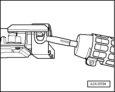
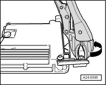
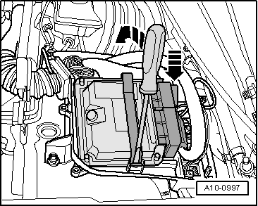
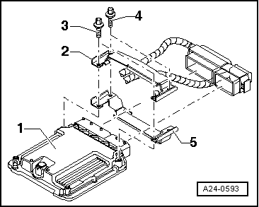
–  Release retaining tabs -arrows- and unplug connectors -1 and 2- from engine control unit.
–  Take out old engine control unit -J623- and install new engine control unit -J623-.
Installing
Installation is performed in the reverse sequence.
–  After installation, the locking plate must be re-fitted on the engine control unit -J623-.
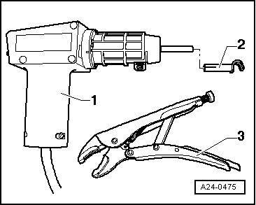
–  Clean threaded holes for shear bolts to remove any residue from locking fluid. This can be done using a thread tap.
–  Always use new shear bolts.
The procedure required after connecting the new engine control unit is described in the Guided Fault Finding or Guided Functions.
–  Activate engine control unit on vehicle diagnosis and service information system -VAS 5052- in „Guided Functions“ mode, „J623 - Renew engine control unit, further steps“.
–  The injector delivery calibration and the injector voltage calibration must additionally be re-adapted in the engine control unit -J623- after the control unit has been renewed (these functions influence engine power and exhaust emissions).
–  On vehicles with particulate filter the current mileage (km) reading must be stored in the engine control unit via an adaption procedure.
  A10-0762

Ignition system, glow plug system > < Wiring and component check with test boxV.A.G 1598/42