| –
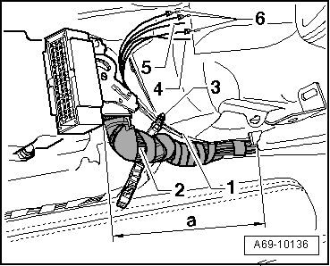
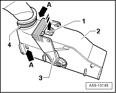
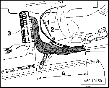
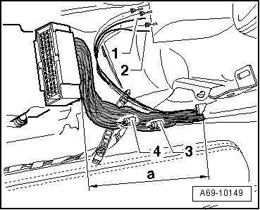
| In area -a- locate connector -A 139-, terminal 15 (connector with black wires) -3-. |
| –
| Separate one black wire leading out of connector -A 139- -3-. |
| –
| Join separated black wire and black wire -2- from wiring harness to be retrofitted using wiring harness repair set -VAS 1978- → Electrical system; Rep. Gr.97. |

WARNING | Observe general instructions for repair work on vehicle electrical system, as well as notes on repairing wiring harnesses, connectors and wiring → Electrical system; Rep. Gr.97. |
|

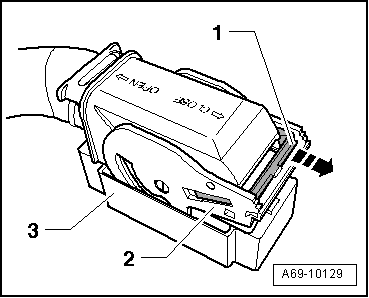
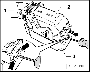
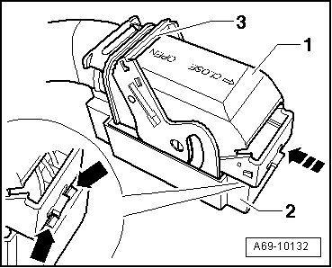
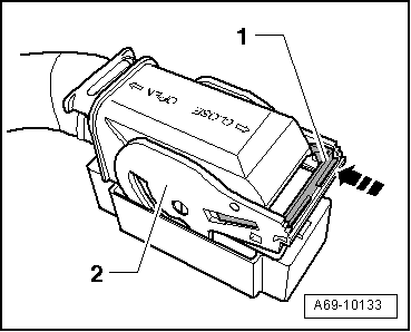
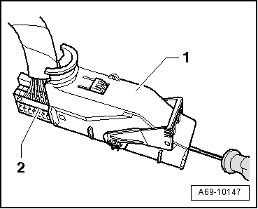
Note | For ease of illustration, closing and plugging-in of the multi-pin connector at the airbag control unit -J234- are described on the basis of a single multi-pin connector. |
|
|
|