audi Workshop Repair Guides

Audi Workshop Service and Repair Manuals

Removing and installing fixed backrest fabric and upholstery > < Removing and installing split backrest cover and upholstery > MY 1998
General Body Assembly, Interior (Repair groups 68, 69, 70, 72, 74)
Rear seat covers and padding
Removing and installing split backrest cover and upholstery MY 1998 ä
 
A74-0086

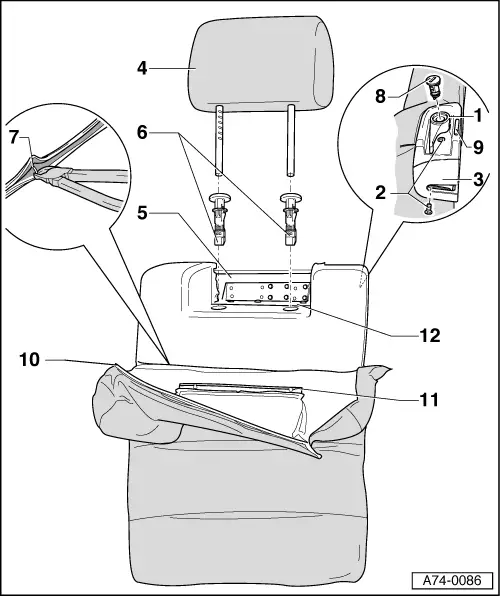
Removing and installing fabric and upholstery for 1/3 backrest

  • ◆ Removing
    • ‒ Removing backrest
    • ‒ Unscrew bolts -2- (2x) of lock trim -3-.
    • ‒ Remove head restraint -4- by pressing button on left head restraint guide-6-.
    • ‒ Remove head restraint guide -6- => Fig.:2
    • ‒ Lever fastening strip -10- out of backrest shell -5-.
    • ‒ Use screwdriver to lever shaped strip -11- out of mount -12-.
    • ‒ Snip off staples -7- and remove seat cover.
 
A74-0086
  • ◆ Installing
    • ‒ Use new staples and upholstery stapling pliers V.A.G 1634 for fitting.
  • Locking lever
    • ‒ Unscrew bolts -2- (2x) in lock trim -3-.
    • ‒ Detach locking lever from underneath at engaging hooks (2x).
    • ‒ Use screwdriver to lever out locking lever at top.
  • Bolts
  • Lock trim
    • ‒ When installing, screw in upper bolt first, then lower bolt.
 
A74-0086
  • Head restraint

Rear outer head restraints are not identical to front head restraints. If all head restraints are removed, attach adhesive tapes as identification.

  • Backrest panel
  • Head restraint guide
  • Staples
  • Lock cylinder
    • ◆ Removing and installing lock cylinder involves use of ignition key.
    • ‒ Remove locking lever.
    • ‒ Use screwdriver to lever out retaining tabs and at the same time press out lock cylinder -8-.
 
A74-0086
  • Warning indicator
    • ◆ When backrest is locked in position, pin protrudes 1-2 mm above lock trim.
    • ◆ When backrest is not locked, pin protrudes approx. 20 mm above lock trim and red mark is visible.
  • Rear fastening strip (all-round)
  • Shaped strip
  • Retainer
 
A74-0087

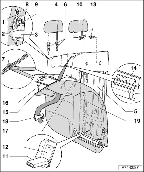
Removing and installing fabric and upholstery for 2/3 backrest

  • ◆ Removing
    • ‒ Removing backrest => Page 72-118
    • ‒ Unscrew bolts -2- (2x) at lock trim -3-.
    • ‒ Remove head restraint -4- by pressing button on left head restraint guide -6-.
    • ‒ Remove centre head restraint -10- by pressing buttons on left and right head restraint guides -13-.
    • ‒ Remove centre arm rest -11- => Page 74-46
    • ‒ Remove ski bag -12- => Page 74-47
    • ‒ Remove head restraint guide -13- => Fig.: 1
 
A74-0087
    • ‒ Remove head restraint guide -6- => Fig.:2
    • ‒ Lever fastening strip -15- out of backrest shell -5-.
    • ‒ Lever out trim for three-point belt -18- with screwdriver
    • ‒ Detach hooks -17- from wire clips -19-.
    • ‒ Use screwdriver to lever out shaped strip -16- out of mount -14-.
    • ‒ Snip off staples -7- and remove seat cover.
  • ◆ Installing
    • ‒ Use new staples and upholstery stapling pliers V.A.G 1634 for fitting.
 
A74-0087

Check the following points after completing installation of backrest:

Seat belt guide fitting and webbing must not make contact with or rub against foam parts or fabric.

Guide fitting must follow all movements of belt webbing.

Belt webbing must run freely in all directions.

  • Locking lever
    • ‒ Unscrew bolts -2- (2x) at lock trim -3-.
    • ‒ Detach locking lever from underneath at engaging hooks (2x).
    • ‒ Use screwdriver to lever out locking lever at top.
  • Bolts
 
A74-0087
  • Lock trim
    • ‒ When installing, screw in upper bolt first, then lower bolt.
  • Outer head restraint

Rear outer head restraints are not identical to front head restraints. If all head restraints are removed, attach adhesive tapes as identification.

  • Backrest panel
  • Head restraint guide
    • ‒ Always fit guide piece with button on the left side.
    • ◆ The button should always face towards the left.
  • Staples
 
A74-0087
  • Lock cylinder
    • ◆ Removing and installing lock cylinder involves use of ignition key.
    • ‒ Remove locking lever.
    • ‒ Use screwdriver to lever out retaining tabs and at the same time press out lock cylinder.
  • Warning indicator
    • ◆ When backrest is locked in position, pin protrudes 1 - 2 mm above lock trim.
    • ◆ When backrest is not locked, pin protrudes approx. 20 mm above lock trim and red mark is visible.
  • Centre head restraint
  • Centre armrest
 
A74-0087
  • Ski bag
    • ◆ Cutting ski bag with new fabric => Page 74-48
  • Centre head restraint guide
    • ◆ Both head restraint guides are fitted with buttons.
    • ◆ The button should always face towards the left.
  • Fastening groove
  • Rear fastening strip (all-round)
  • Fastening strip at head restraint
  • Hook
  • Trim for three-point belt
    • ◆ Removing => Page 69-25
  • Wire bracket
 
A74-0053

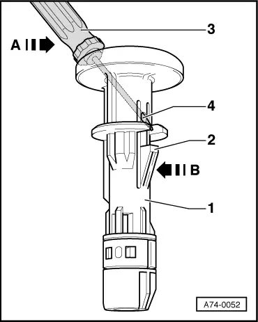
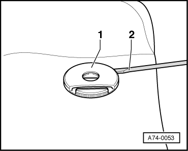
Fig.:1    Removing centre head restraint guides

  • ‒ Use screwdriver -2- to lever out centre head restraint guides -1-.

 
A74-0052

Fig.:2    Removing head restraint guides

For improved clarity, head restraint guide -1- is shown removed.

  • ‒ Insert padding needle or screwdriver -3- with maximum width of 2 mm into hole -4- (hole -4- is opposite retaining clip for head restraint guide).
  • ‒ By levering screwdriver -3- in direction of arrow -A- press retainer tab -2- in direction of arrow -B- and in doing so pull out head restraint guide -1-.

Removing and installing fixed backrest fabric and upholstery > < Removing and installing split backrest cover and upholstery > MY 1998