audi Workshop Repair Guides

Audi Workshop Service and Repair Manuals

Basic setting > < Charging pump with 2 connections
Brake System
Servicing ESP hydraulic unit
Removing and installing ESP (electronic stability program) hydraulic pump

Special tools and workshop equipment required

Plug repair set, Part no. 1H0 698 311A

V.A.G 1551 or V.A.G 1552

V.A.G 1869

 
A45-0062

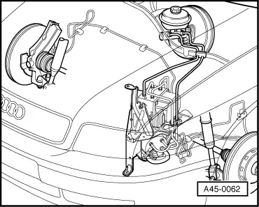
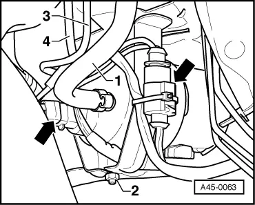
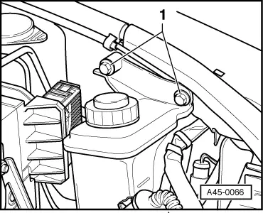
→ Fitting location

The ESP hydraulic pump is located in the engine compartment on the left beneath the hydraulic control unit.

Removing

  • ‒ Vehicle standing on its wheels over lifting platform.

Note:

  • ◆ Switch off the ignition before removing and installing components. If the vehicle is equipped with a coded radio, obtain the security code before disconnecting the earthing strap of the battery.
 
A45-0063
  • ‒ Disconnect battery.

=> Electrical System; Repair group 27; Battery

  • ‒ Remove front left wheel.
  • ‒ Raise vehicle.
  • ‒ Remove front left wheel housing liner.
  • ‒ → Detach connectors (see arrows).

 
A45-0064
  • ‒ Remove cover for hydraulic fluid reservoir.
  • ‒ → Unclip attachment strip for cable at bracket.
 
A45-0065
  • ‒ → Release securing screws - arrows- and swivel coolant expansion reservoir to one side.
    • ‒ Tightening torque 6 Nm

 
A45-0066
  • ‒ → Release bolts -1- for hydraulic fluid reservoir and swivel away to one side.
    • ‒ Tightening torque 10 Nm
    • ‒ Note the locking element (rubber grommet) at the bottom when inserting.

Note:

 
A45-0063
  • ◆ Protect the engine compartment against escaping brake fluid.
  • ‒ → Release hose clamp of suction hose -1- and detach.
  • ‒ Unbolt brake pipes -3- and -4-.
  • ‒ Seal brake pipes and threaded holes with plugs from repair set Part No. 1H0 698 311 A.
  • ‒ Unclip brake pipes from holder.
  • ‒ Unscrew hexagon nut -2-.
  • ‒ Unscrew hexagon nuts for holder =>Item 45-32.
  • ‒ Working from the engine compartment, lift the holder with the hydraulic unit and the hydraulic pump about 30 mm and take them out.

Installing

Pay special attention to the following on installation:

  • ◆ Only remove sealing plugs on new hydraulic control unit when the corresponding brake pipe is about to be fitted. Otherwise brake fluid will leak =>Paintwork and Corrosion Protection

Bleeding brake system with brake filling and bleeding unit V.A.G 1869

  • ‒ Connect V.A.G 1869.
  • ‒ Open bleeder screws in the specified order and bleed brake calipers (assist as required with pedal pressure).

Bleeding sequence

  •     1 -    Rear left brake caliper
  •     2 -    Front right brake caliper
  •     3 -    Rear right brake caliper
  •     4 -    Front left brake caliper

Basic setting > < Charging pump with 2 connections