audi Workshop Repair Guides

Audi Workshop Service and Repair Manuals

Charging refrigerant circuit with air conditioner service station > < Discharging refrigerant circuit with air conditioner service station
Evacuating refrigerant circuit with air conditioner service station
l  The work procedure must always be performed as described in the operating instructions of the air conditioner service station.
l  Quantity of refrigerant oil in refrigerant circuit checked and if necessary corrected → Chapter.
l  Quantity of refrigerant in air conditioner service station checked
The refrigerant circuit must be evacuated before it is filled with refrigerant. In addition, moisture is removed from the circuit.
Leaks can be detected on evacuating the refrigerant circuit.
Evacuating:
  Caution
t  Do not start the engine during the evacuating procedure and while there is a vacuum in the refrigerant circuit.
t  The air conditioner compressor may be damaged if the engine is started whilst there is a vacuum in the refrigerant circuit.
t  Always charge the refrigerant circuit before starting the engine.
–  Switch off ignition.
–  Connect air conditioner service station to power supply.
–  Connect the charging hoses of the air conditioner service station to the vehicle refrigerant circuit with quick-release coupling adapters (refer to vehicle-specific refrigerant circuit) → Heating, air conditioning; Rep. gr.87 or → Air conditioning; Rep. gr.87 (vehicle-specific workshop manual).
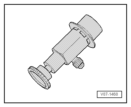
–  Screw in the handwheel of the quick-release coupling adapters to the extent required to reliably open the valves of the service connections (take care not to open the valve too far).
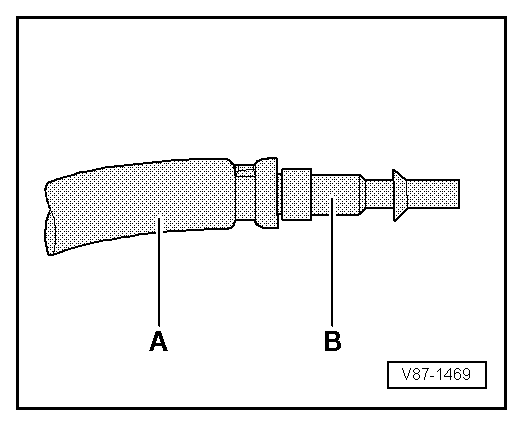
  Note
If you intend to measured the pressure on only one side of the refrigerant circuit after charging the system (on vehicles with a service connection), use the valve adapter and filler hose with valve opener → Chapter.
–  Switch on air conditioner service station and evacuate refrigerant circuit for at least 30 minutes. In this process, the pressure reading must be less than 10 mbar absolute (corresponding to a vacuum of 990 mbar).
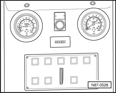
  Note
On the air conditioner service station V.A.G 1885 (for currently available air conditioner service stations, refer to → V.A.G workshop equipment catalogue), the two green LEDs light at this pressure for example.
–  Switch off the air conditioner service station and allow to stand for at least 1 hour.
l  If the vacuum display (LED chain) does not change, the system is free of leaks and can be charged.
  Note
t  With V.A.G 1885 for example (for currently available air conditioner service stations, refer to → V.A.G workshop equipment catalogue), a current vacuum display (LED) is only obtained after pressing the Evacuation button again.
   
t  If, with this air conditioner service station, the upper (green) LEDs do not light immediately after switching on, either the refrigerant circuit is leaking or there is still residual moisture/refrigerant in the circuit.
Proceed as follows if the vacuum is not maintained or an adequate vacuum cannot be generated:
t  The pressure in the refrigerant circuit only increases slowly following evacuation, e.g. due to the evaporation of refrigerant from the refrigeration oil.
–  If it is not certain whether the refrigerant circuit is really leak-proof, repeat evacuation and observe the vacuum display over a lengthy period. Charging can only be performed once the vacuum is maintained.
–  It it is certain that there are no leaks in the refrigerant circuit, charging can be performed.
t  In the event of a leak of such a magnitude that the ingress of air on evacuation is already sufficient to prevent the air conditioner service station generating an adequate vacuum or the vacuum gauge already indicates the ingress of air and the loss of vacuum immediately after switching off the air conditioner service station.
–  Determine the leakage location in the refrigerant circuit as follows:
  Note
t  A major leak can be determined for example by building up a pressure of max. 15 bar in the refrigerant circuit with pure, dry compressed air or with nitrogen → Chapter. If the leak is of sufficient magnitude, the leakage location will be revealed by the noise of the gas escaping.
  N87-0528
t  Apply the compressed air or the nitrogen to the closed refrigerant circuit by way of the service connection to which a quick-release coupling adapter for service connections has been attached.
  V87-1468
t  The quick-release coupling adapter for service connections can be connected to the workshop compressed air system using for example a modified charging hose -A- (e.g. with a 5/8"-18 UNF thread, depending on the thread at the quick-release coupling adapter) and an appropriate adapter -B- → Chapter. To prevent the ingress of moisture, oil and dirt from the workshop compressed air system into the air conditioner refrigerant circuit, additional use is to be made for example of a combined fine filter unit for compressed air systems (oil, dirt and water separator as used for painting facilities), which is to be fitted between the compressed air system and the charging hose -A- → Workshop equipment catalogue.
  V87-1469
t  Using a pressure gauge set with nitrogen pressure reducer -1- (max. reducing pressure: 15 bar), a compressed-gas cylinder -3- filled with nitrogen can be connected to the service connection (quick-release coupling adapter for service connections attached) at the closed refrigerant circuit → Chapter with a charging hose -2- (e.g. with a 5/8"-18 UNF thread).
–  Slowly increase the pressure in the refrigerant circuit to max. 15 bar.
  WARNING
t  There may be an uncontrolled flow of nitrogen out of the cylinder.
t  Always work with pressure reducers for nitrogen cylinders (max. working pressure 15 bar).
t  For leak detection with nitrogen (max. permissible operating pressure 15 bar) always work with pressure reducers for nitrogen cylinders.
t  Use appropriate extraction units to draw off the gas mixture escaping from the components.
–  Determine the leakage location by way of the noise caused by the escaping gas at this point.
–  Eliminate the leakage.
–  Evacuate again and observe the vacuum display over a period of hours. Charging can only be performed once the vacuum is maintained.
t  In the event of a leakage of a magnitude permitting the ingress of no or very little air and the air conditioner service station can generate an adequate vacuum. The vacuum display does not increase or only increases very slowly after switching off the air conditioner service station, indicating that air is only ingressing and vacuum is being lost through a minor leak.
–  Pour 100 g of refrigerant into the circuit and use an electronic leak detector to locate and eliminate any leak → Chapter or pour in refrigerant with UV contrast medium and use the leak detection system VAS 6201 to search for and eliminate the leak in the refrigerant circuit → Chapter.
–  Discharge the refrigerant circuit if necessary → Chapter.
–  Evacuate the refrigerant circuit and observe the vacuum display again over a period of hours. Charging can only be performed once the vacuum is maintained.
  V87-1244

Charging refrigerant circuit with air conditioner service station > < Discharging refrigerant circuit with air conditioner service station