-
‒ → Connect the adapter cables V.A.G 1598/11 and V.A.G 1598/12 to the detached connectors of the operating and display unit -E87.
Notes:
-
◆ Do not connect the operating and display unit -E87 (except for test steps 5.10, 5.11 and 5.12 in vehicles from Model Year 1997).
-
◆ For measurement purposes, connect test box V.A.G 1598A to the respective adapter cable.
-
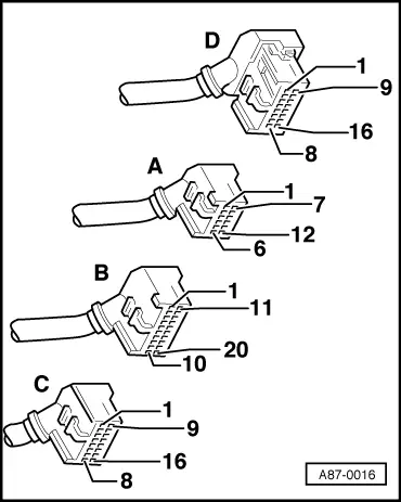
◆ On the adapter cable V.A.G 1598/12, the socket assignment is identical to the connector assignment of the operating and display unit -E87.
-
◆ On the adapter cable V.A.G 1598/11, the socket assignment is not identical to the connector assignment of the operating and display unit -E87. =>Connector assignment, Page 01-142.
Pin assignment of test box V.A.G 1598 A with adapter cable V.A.G 1598/11
Notes:
-
◆ With adapter cable V.A.G 1598/11, the contact assignment of connectors A and B is not identical to the socket assignment on the test box V.A.G 1598 A.
-
◆ With adapter cable V.A.G 1598/11, the contact assignment of connector C is identical to the socket assignment on the test box V.A.G 1598 A.
-
◆ The contact assignment of connector D with adapter cable V.A.G 1598/12 is identical to the assignment of the sockets on the test box V.A.G 1598A.
-
◆ Due to the use of two adapter cables for the connectors for the operating and display unit -E87(V.A.G 1598/11 and 12), no earth connection is possible when the adapter cable V.A.G 1598/11 is connected. To perform the electrical tests, it is therefore necessary in some test steps to take measurements against a suitable earthing point on the vehicle body or to use a second V.A.G 1598 A (when the adapter cable 1598/12 is connected, sockets 14 and 15 are earthed).
|
|
|---|
|
Connector A
contact
|
V.A.G 1598 A Socket
|
Connector B
contact
|
V.A.G 1598 A Socket
|
Connector B
contact
|
V.A.G 1598 A Socket
|
|
1
|
41
|
1
|
21
|
13
|
33
|
|
2
|
42
|
2
|
22
|
14
|
34
|
|
3
|
43
|
3
|
23
|
15
|
35
|
|
4
|
44
|
4
|
24
|
16
|
36
|
|
5
|
45
|
5
|
25
|
17
|
37
|
|
6
|
46
|
6
|
26
|
18
|
38
|
|
7
|
47
|
7
|
27
|
19
|
39
|
|
8
|
48
|
8
|
28
|
20
|
40
|
|
9
|
49
|
9
|
29
|
|
|
|
10
|
50
|
10
|
30
|
|
|
|
11
|
51
|
11
|
31
|
|
|
|
12
|
52
|
12
|
32
|
|
|
Overview of the electrical tests on the operating and display unit -E87
|
|
|---|
|
Test step
|
Component tested
|
Page
|
|
1
|
- Power supply and earth connection for the operating and display unit -E87
- Illumination of the operating and display unit -E87 (only vehicles up to Model Year 1997)
- Illumination of the operating and display unit -E87 (only vehicles from Model Year 1998)
- Signal for "ignition off time" (only vehicles from Model Year 1997)
|
01-151
|
|
2
|
- Temperature sensors/pickups -G17, -G56, -G89
- -G110 (only vehicles up to Model Year 1996)
- -G191, -G192 (only vehicles from Model Year 1997)
|
01-155
|
|
3
|
- Fresh-air blower-V2 and fresh-air blower control unit -J126
|
01-158
|
|
4
|
- Positioning motors for the air conditioner and associated potentiometers -V68/-G92, -V70/-G112, -V71/-G113, -V85/-G114
|
01-160
|
|
5
|
- Air conditioner compressor speed sensor -G111 (only vehicles up to Model Year 1996 with Zexel compressors and 6-cylinder engines)
- System-operated switches -F73, -F118 (only vehicles up to Model Year 1996)
- Temperature sensor blower-V42 (not with -E87 with only one display)
- "Air conditioner intervention" output, signal for "engine temperature too high"
- Pressure switch for air conditioner -F129 (only vehicles from Model Year 1997)
|
01-173
|
|
6
|
- Magnetic clutch relay -J44
- Actuation of the radiator fan -V7 (speed 1)
|
01-175
|
Test step 1:
Power supply, earth connection, illumination of the operating and display unit -E87 and signal for "ignition off time"
|
|
|---|
|
Select measuring range on hand-held multimeter V.A.G 1526: Voltage measurement (20V =)
▪ Adapter cable V.A.G 1598/12 connected
|
|
Test step
|
V.A.G 1598 A Socket
|
Testing of
|
▪ Test conditions
- Additional operations
|
Specified value
|
Remedies if specified value not attained
|
|
1.1
|
9
+
14
|
- Terminal 75 and earth connection on the -E87 (up to Model Year 1996)
- Terminal 15 and earth connection on the -E87 (from Model Year 1997)
|
▪ Ignition switched on
|
- approx. battery voltage
|
- Use current flow diagram to repair power supply or earth connection
|
|
1.2
|
9
+
15
|
Earth connection at the -E87
|
▪ Ignition switched on
|
- approx. battery voltage
|
- Use current flow diagram to repair earth connection to -E87
|
|
|
|---|
|
Select measuring range on hand-held multimeter V.A.G 1526: Resistance measurement (200 ω)
▪ Adapter cable V.A.G 1598/11 connected
|
|
Test step
|
V.A.G 1598 A Socket
|
Testing of
|
▪ Test conditions
- Additional operations
|
Specified value
|
Remedies if specified value not attained
|
|
1.3
|
49
+
52
|
Earth connection at the -E87
|
▪ Ignition off
|
- Less than 20 ω
|
- Use current flow diagram to repair earth connection to -E87
|
|
Select measuring range on hand-held multimeter V.A.G 1526: Voltage measurement (20 V =)
▪ Adapter cable V.A.G 1598/11 connected
|
|
1.4 1)
|
13
+
Earth
|
Power supply, terminal 30 of -E87
|
▪ Ignition off
|
- approx. battery voltage
|
- Use current flow diagram to rectify power supply to terminal 30 to or earth connection to -E87
|
1) Only perform test step on vehicles up to Model Year 1996.
|
|
|---|
|
Select measuring range on hand-held multimeter V.A.G 1526: Voltage measurement (20 V =)
▪ Adapter cable V.A.G 1598/11 connected
|
|
Test step
|
V.A.G 1598 A Socket
|
Testing of
|
▪ Test conditions
- Additional operations
|
Specified value
|
Remedies if specified value not attained
|
|
1.52)
|
7
+
Earth3)
|
Power supply, terminal 58 of -E87
|
▪ Ignition switched on
▪ Side lights on
|
- approx. battery voltage
|
- Use current flow diagram to rectify power supply to terminal 58 to or earth connection to -E87
|
|
1.62)
|
7
+
Earth3)
|
Power supply, terminal 58 of -E87
|
▪ Ignition switched on
▪ Side lights off
|
- Less than 2 V
|
- Use current flow diagram to locate and rectify short to positive to -E87
|
2) Only perform test step on vehicles up to Model Year 1997.
3) Earth is connected, for example, to connector D, contacts 14 and 15.
|
|
|---|
|
Select measuring range on hand-held multimeter V.A.G 1526: Voltage measurement (20 V =)
▪ Adapter cable V.A.G 1598/11 connected
|
|
Test step
|
V.A.G 1598 A Socket
|
Testing of
|
▪ Test conditions
- Additional operations
|
Specified value
|
Remedies if specified value not attained
|
|
1.72)
|
45
+
Earth3)
|
Power supply terminal 58d of the -E87
|
▪ Ignition switched on
▪ Side lights on
|
- Governed by brightness setting for instrument illumination
|
- Use current flow diagram to locate and rectify open circuit or short to positive to -E87
|
|
1.82)
|
45
+
Earth3)
|
Power supply terminal 58d of the -E87
|
▪ Ignition switched on
▪ Side lights off
|
- Less than 2 V
|
- Use current flow diagram to locate and rectify short to positive to -E87
|
2) Only perform test step on vehicles up to Model Year 1997.
3) Earth is connected, for example, to connector D, contacts 14 and 15.
|
|
|---|
|
Select measuring range on hand-held multimeter V.A.G 1526: Voltage measurement (20 V =)
▪ Adapter cable V.A.G 1598/11 connected
|
|
Test step
|
V.A.G 1598 A Socket
|
Testing of
|
▪ Test conditions
- Additional operations
|
Specified value
|
Remedies if specified value not attained
|
|
1.9 4)
|
7
+
Earth3)
|
Power supply, terminal 58s of the -E87
|
▪ Ignition switched on
▪ Side lights on
|
- 0...12 V
|
- Use current flow diagram to locate and rectify open circuit or short to positive to -E87
|
|
1.10 4)
|
7
+
Earth3)
|
Power supply, terminal 58s of the -E87
|
▪ Ignition switched on
▪ Side lights off
|
- approx. 0 V
|
- Use current flow diagram to locate and rectify short to positive to -E87
|
3) Earth is connected, for example, to connector D, contacts 14 and 15.
4) Only perform test step on vehicles as of Model Year 1998.
Note:
The voltage at terminal 58s is governed by the setting of the instrument illumination control.
|
|
|---|
|
Select measuring range on hand-held multimeter V.A.G 1526: Voltage measurement (20 V =)
▪ Adapter cable V.A.G 1598/11 connected
|
|
Test step
|
V.A.G 1598 A Socket
|
Testing of
|
▪ Test conditions
- Additional operations
|
Specified value
|
Remedies if specified value not attained
|
|
1.114)
|
45
+
Earth3)
|
Power supply terminal 58d of the -E87
|
▪ Ignition switched on
▪ Side lights on
|
- 0...12 V
|
- Use current flow diagram to repair open circuit or short to positive to -E87
|
|
1.124)
|
45
+
Earth3)
|
Power supply terminal 58d of the -E87
|
▪ Ignition switched on
▪ Side lights off
|
- 0...12 V
|
- Use current flow diagram to repair open circuit or short to positive to -E87
|
3) Earth is connected, for example, to connector D, contacts 14 and 15.
4) Only perform test step on vehicles as of Model Year 1998.
Notes:
-
◆ The voltage at terminal 58d is generated as a square wave signal by the dash panel insert; the brightness of the displays on the operating and display unit -E87 is determined by the actuation period. The averaged value is displayed on the measuring instrument.
-
◆ The actuation period at terminal 58d is governed by the setting of the illumination control and the brightness level determined by the photosensor in the dash panel insert.
|
|
|---|
|
Voltage tester V.A.G 1527 B
▪ Adapter cable V.A.G 1598/11 connected
|
|
Test step
|
V.A.G 1598 A Socket
|
Testing of
|
▪ Test conditions
- Additional operations
|
Specified value
|
Remedies if specified value not attained
|
|
1.13 5)
|
33
+
Earth3)
|
Signal for "ignition off time"
|
▪ Ignition switched on
|
- LED in voltage tester lights
|
- Use current flow diagram to locate and rectify short circuit or open circuit
|
|
1.14 5)
|
33
+
Earth3)
|
Signal for "ignition off time"
|
▪ Ignition switched on
Start engine
|
- LED in voltage tester lights
- When the engine is started, the LED in the voltage tester flickers briefly (time signal) and then remains lit
|
- Use current flow diagram to locate and rectify short circuit or open circuit
|
3) Earth is connected, for example, to connector D, contacts 14 and 15.
5) Only perform test step on vehicles as of Model Year 1997.
|
|
|---|
|
Select measuring range on hand-held multimeter V.A.G 1526: Voltage measurement (20 V =)
▪ Adapter cable V.A.G 1598/11 connected
|
|
Test step
|
V.A.G 1598 A Socket
|
Testing of
|
▪ Test conditions
- Additional operations
|
Specified value
|
Remedies if specified value not attained
|
|
1.154)
|
46
+
Earth3)
|
Power supply, terminal 58 of -E87
|
▪ Ignition switched on
▪ Side lights on
|
- approx. battery voltage
|
- Use current flow diagram to locate and rectify open circuit or short to earth in the wiring to the -E87
|
|
1.164)
|
46
+
Earth3)
|
Power supply, terminal 58 of -E87
|
▪ Ignition switched on
▪ Side lights off
|
- Less than 2 V
|
- Use current flow diagram to locate and rectify short to positive in the wiring to the -E87
|
3) Earth is connected, for example, to connector D, contacts 14 and 15.
4) Test step only to be performed on vehicles with an operating and display unit with one display.
|
|
|---|
|
Select measuring range on hand-held multimeter V.A.G 1526: Voltage measurement (20V =)
▪ Adapter cable V.A.G 1598/12 connected
|
|
Test step
|
V.A.G 1598 A Socket
|
Testing of
|
▪ Test conditions
- Additional operations
|
Specified value
|
Remedies if specified value not attained
|
|
1.17 4)
|
8
+
14
|
- Terminal 15 and earth connection on the -E87 (power supply for the magnetic clutch)
|
▪ Ignition switched on
|
- approx. battery voltage
|
- Use current flow diagram to repair power supply or earth connection
|
4) Test step only to be performed on vehicles with an operating and display unit with one display.
Test step 2:
Temperature sensor/sender
|
|
|---|
|
Select measuring range on hand-held multimeter V.A.G 1526: Resistance measurement (20 kω/ 200 kω)
▪ Adapter cable V.A.G 1598/11 connected
|
|
Test step
|
V.A.G 1598 A Socket
|
Testing of
|
▪ Test conditions
- Additional operations
|
Specified value
|
Remedies if specified value not attained
|
|
2.1
|
48
+
52
|
Outside temperature sensor -G17
|
▪ Ignition off
Measure temperature at the sensor fitting location
|
- Governed by the temperature at the sensor/pickup fitting location
|
- Use current flow diagram to locate and rectify short circuit, open circuit or contact resistance
|
|
2.26)
|
50
+
52
|
Dash panel temperature sensor -G56
|
|
|
=> Table, Page 01-156
|
- Renew temperature sensor/pickup
|
|
2.3
|
47
+
52
|
Fresh air intake duct temperature sensor -G89
|
|
|
|
6) Test step only to be performed with operating and display unit -E87 with two displays.
|
|
|---|
|
Select measuring range on hand-held multimeter V.A.G 1526: Resistance measurement (20 kω/ 200 kω)
▪ Adapter cable V.A.G 1598/11 connected
|
|
Test step
|
V.A.G 1598 A Socket
|
Testing of
|
▪ Test conditions
- Additional operations
|
Specified value
|
Remedies if specified value not attained
|
|
2.4 2)
|
27
+
52
|
Air conditioner refrigerant temperature sensor -G110
|
▪ Ignition off
Measure temperature at the sensor fitting location
|
- Governed by the temperature at the sensor fitting location
|
- Use current flow diagram to locate and rectify short circuit, open circuit or contact resistance
|
|
2.5 5)
|
26
+
49
|
Centre vent temperature sensor
-G191
|
|
|
=> Table, Page 01-156
|
- Replace temperature sensor
|
|
2.6 5)
|
25
+
49
|
Footwell vent temperature sensor
-G192
|
|
|
|
2) Test step only to be performed on vehicles up to Model Year 1996 with 6-cylinder engine and Zexel compressor.
5) Only perform test step on vehicles as of Model Year 1997.
Temperature-dependent resistances of sensors/pickups
|
|
|---|
|
Temperature
measured at sensor/sender fitting location
°C
|
Resistance of
sensor -G56
kω
|
Resistance of sensors -G17 and -G89
kω
|
Resistance of
sensor -G110
kω
|
Resistance of
sensor -G191
kω
|
Resistance of
sensor -G192
kω
|
|
- 30
|
(52.70)
|
18.10
|
26.50
|
(141.00)
|
(52.70)
|
|
- 20
|
(28.60)
|
9.95
|
14.70
|
(85.00)
|
(28.60)
|
|
-10
|
16.20
|
5.59
|
9.20
|
(47.00)
|
(16.20)
|
|
0
|
9.40
|
3.28
|
5.60
|
29.00
|
9.40
|
|
5
|
7.27
|
2.54
|
4.63
|
23.20
|
7.27
|
|
10
|
5.66
|
1.99
|
3.67
|
18.60
|
5.66
|
|
15
|
4.45
|
1.57
|
3.06
|
15.00
|
4.45
|
|
20
|
3.50
|
1,25
|
2.45
|
12.20
|
3.50
|
|
25
|
2.79
|
1.00
|
2.06
|
10.00
|
2.79
|
|
30
|
2.23
|
0.80
|
1.67
|
8.20
|
2.23
|
|
|
|---|
|
Temperature
measured at sensor/sender fitting location
°C
|
Resistance of
sensor -G56
kω
|
Resistance of sensors -G17 and -G89
kω
|
Resistance of
sensor -G110
kω
|
Resistance of
sensor -G191
kω
|
Resistance of
sensor -G192
kω
|
|
35
|
1.80
|
0.65
|
1.41
|
6.80
|
1.80
|
|
40
|
1.45
|
0.53
|
1.16
|
5.70
|
1.45
|
|
50
|
0.97
|
0.36
|
0.83
|
4.00
|
0.97
|
|
60
|
0.67
|
0.25
|
0.60
|
2.90
|
0.67
|
|
70
|
0.47
|
|
0.44
|
2.10
|
0.47
|
|
80
|
0.33
|
|
0.33
|
|
|
|
90
|
|
|
0.24
|
|
|
|
100
|
|
|
0.19
|
|
|
Test step 3:
Fresh-air blower-V2 and fresh-air blower control unit -J126
|
Select measuring range on hand-held multimeter V.A.G 1526: Voltage measurement (20 V =)
▪ Adapter cable V.A.G 1598/11 connected
|
|
Test step
|
V.A.G 1598 A Socket
|
Testing of
|
▪ Test conditions
- Additional operations
|
Specified value
|
Remedies if specified value not attained
|
|
3.1
|
16
+
Earth3)
|
Control unit -J126
|
▪ Ignition switched on
|
- Voltage less than 5 V
- Fresh-air blower not running
|
- Use current flow diagram to locate and rectify short to positive in the wiring between -J126 and -E87
Renew control unit -J126
|
|
3.2
|
14
+
Earth3)
|
Power supply for fresh-air blower -V2
|
▪ Ignition switched on
|
- approx. battery voltage
|
- Use current flow diagram to repair power supply
|
|
3.3
|
11
+
Earth3)
|
Power supply for control unit -J126 (via fresh-air blower -V2)
|
▪ Ignition switched on
|
- approx. battery voltage
|
- Use current flow diagram to repair power supply
|
3) Earth is connected, for example, to connector D, contacts 14 and 15.
|
Voltage tester V.A.G 1527 B
▪ Adapter cable V.A.G 1598/11 connected
|
|
Test step
|
V.A.G 1598 A Socket
|
Testing of
|
▪ Test conditions
- Additional operations
|
Specified value
|
Remedies if specified value not attained
|
|
3.41)
|
13
+
16
|
Control unit -J126
|
▪ Ignition switched on
|
- LED in voltage tester lights
|
- Use current flow diagram to locate and rectify open circuit in the wiring between -J126 and -E87
|
|
|
|
|
|
- Fresh air blower is running
|
- Check freedom of movement of fresh-air blower -V2
Renew control unit -J126
|
|
3.55)
|
14
+
16
|
Control unit -J126
|
▪ Ignition switched on
|
- LED in voltage tester lights
|
- Use current flow diagram to locate and rectify open circuit in the wiring between -J126 and -E87
|
|
|
|
|
|
- Fresh air blower is running
|
- Check freedom of movement of fresh-air blower -V2
Renew control unit -J126
|
1) Only perform test step on vehicles up to Model Year 1996.
5) Only perform test step on vehicles as of Model Year 1997.
Test step 4:
Positioning motors for air conditioner and associated potentiometers
Notes:
-
◆ The resistance of potentiometers in the positioning motors (specified value: 3.6... 5.7 kωbetween contacts 3 and 4) can only be measured directly at the positioning motor (parallel connection).
-
◆ The resistance of the potentiometers in the positioning motors (between contacts 3 and 5 and contacts 4 and 5) is governed by the setting of the positioning motor; it must only be measured with the positioning motorinstalled. The upper specified value is not achieved in test steps 4.1 and 4.2. (To achieve the upper specified value, it would be necessary to pull all the connectors of the other positioning motors during the measurement - parallel connection).
-
◆ If the -E87 detects the fault "potentiometer short to earth" or "open circuit/short to positive", check all the potentiometers (in the 4 positioning motors) and the associated wiring.
-
◆ If several positioning motors are simultaneously indicated as faulty in the fault memory and no fault is detected in test step 4, check the positioning motor for a short circuit between the individual positioning motors (e.g. between -V85 and -V70, measured value between sockets 3 and 4 must be ∞ω).
-
◆ Up to Model Year 1996, the installation of the positioning motor -V71 was dependent upon equipment and it is therefore not installed in all vehicles (e.g. not in right-hand drive vehicles).
-
◆ In right-hand drive vehicles, contacts 1 and 2 and contacts 3 and 4 on the air-flow flap positioning motor -V71 are interchanged.
=> Current Flow Diagrams, Electrical Fault-finding and Fitting Locations binder
|
|
|---|
|
Select measuring range on hand-held multimeter V.A.G 1526: Resistance measurement (20 kω)
▪ Adapter cable V.A.G 1598/11 connected
|
|
Test step
|
V.A.G 1598 A Socket
|
Testing of
|
▪ Test conditions
- Additional operations
|
Specified value
|
Remedies if specified value not attained
|
|
4.1
|
52
+
28/
29/
37/
30
|
Potentiometer (in the positioning motor)
-G 92 (-V68)
-G112 (-V70)
-G113 (-V71)
-G114 (-V85)
|
▪ Ignition off
|
- Greater than 0.1 kω and less than 5.7 kω (depends on the setting of the positioning motor)
|
- Use current flow diagram to locate and rectify short circuit, open circuit or contact resistance
Renew positioning motor
|
|
4.2
|
8
+
28/
29/
37/
30
|
Potentiometer (in the positioning motor)
-G 92 (-V68)
-G112 (-V70)
-G113 (-V71)
-G114 (-V85)
|
▪ Ignition off
|
- Greater than 0.1 kω and less than 5.7 kω (depends on the setting of the positioning motor)
|
- Use current flow diagram to locate and rectify short circuit, open circuit or contact resistance
Renew positioning motor
|
|
4.3
|
14
+
28/
29/
37/
30
|
Potentiometer (in the positioning motor)
-G 92 (-V68)
-G112 (-V70)
-G113 (-V71)
-G114 (-V85)
|
▪ Ignition off
|
- ∞ ω
|
- Use the current flow diagram to locate and rectify short to earth.
Renew positioning motor
|
|
|
|---|
|
Select measuring range on hand-held multimeter V.A.G 1526: Resistance measurement (200 ω)
▪ Adapter cable V.A.G 1598/12 connected
|
|
Test step
|
V.A.G 1598 A Socket
|
Testing of
|
▪ Test conditions
- Additional operations
|
Specified value
|
Remedies if specified value not attained
|
|
4.4
|
2
+
10
|
Temperature flap positioning motor -V68
|
▪ Ignition off
|
- 20...100ω
|
- Use current flow diagram to locate and rectify short circuit, open circuit or contact resistance
|
|
4.5
|
4
+
12
|
Central flap positioning motor -V70
|
|
- 20...100ω
|
- Renew positioning motor
|
|
4.6
|
5
+
13
|
Air-flow flap positioning motor -V71
|
|
- 20...100ω
|
|
|
4.7
|
3
+
11
|
Footwell/defroster flap positioning motor -V85:
|
|
- 20...100ω
|
|
|
Select measuring range on hand-held multimeter V.A.G 1526: Resistance measurement (20 kω)
▪ Adapter cable V.A.G 1598/12 connected
|
|
Test step
|
V.A.G 1598 A Socket
|
Testing of
|
▪ Test conditions
- Additional operations
|
Specified value
|
Remedies if specified value not attained
|
|
4.8
|
14
+
2/
3/
4/
5
|
Wiring to the positioning motors
-V68
-V85
-V70
-V71
for short to earth
|
▪ Ignition off
|
- ∞ ω
|
- Use the current flow diagram to rectify short to earth
|
|
Select measuring range on hand-held multimeter V.A.G 1526: Voltage measurement (20 V =)
▪ Adapter cable V.A.G 1598/12 connected
|
|
4.9
|
14
+
2/
3/
4/
5
|
Wiring to the positioning motors
-V68
-V85
-V70
-V71
for short to positive
|
▪ Ignition switched on
|
- Less than 1 V
|
- Use the current flow diagram to rectify short to positive
|
Test step 5:
Air conditioner compressor speed sensor -G111, magnetic clutch high-pressure switch -F118, air conditioner low-pressure switch -F73, temperature sensor blower -V42, air conditioner compressor intervention output and engine temperature too high signal
|
Select measuring range on hand-held multimeter V.A.G 1526: Resistance measurement (20 kω)
▪ Adapter cable V.A.G 1598/11 connected
|
|
Test step
|
V.A.G 1598 A Socket
|
Testing of
|
▪ Test conditions
- Additional operations
|
Specified value
|
Remedies if specified value not attained
|
|
5.1 2)
|
5
+
49
|
Air conditioner compressor speed sender -G111
|
▪ Ignition off
|
- 0.8...1.5 kω
|
- Use current flow diagram to locate and rectify open circuit, contact resistance or short circuit
Sender -G111 defective. Send vehicle to an VW/Audi air conditioner service centre
|
2) Test step only to be performed on vehicles up to Model Year 1996 with 6-cylinder engine and Zexel compressor.
|
|
|---|
|
Select measuring range on hand-held multimeter V.A.G 1526: Resistance measurement (20 kω)
▪ Adapter cable V.A.G 1598/11 connected
|
|
Test step
|
V.A.G 1598 A Socket
|
Testing of
|
▪ Test conditions
- Additional operations
|
Specified value
|
Remedies if specified value not attained
|
|
5.2 2)
|
5
+
Earth
|
Air conditioner compressor speed sender -G111
|
▪ Ignition off
|
- greater than 2 kω
|
- Locate and rectify the short circuit using the current flow diagram
Sender -G111 defective. Send vehicle to an VW/Audi air conditioner service centre
|
2) Test step only to be performed on vehicles up to Model Year 1996 with 6-cylinder engine and Zexel compressor.
|
|
|---|
|
Select measuring range on hand-held multimeter V.A.G 1526: Voltage measurement (20 V =)
▪ Adapter cable V.A.G 1598/11 connected
|
|
Test step
|
V.A.G 1598 A Socket
|
Testing of
|
▪ Test conditions
- Additional operations
|
Specified value
|
Remedies if specified value not attained
|
|
5.3 2)
|
5
+
Earth
|
Air conditioner compressor speed sender -G111
|
▪ Engine running
▪ Compressor not running
|
- Less than 1 V
|
- Locate and rectify the short circuit using the current flow diagram
|
|
Select measuring range on hand-held multimeter V.A.G 1526: Voltage measurement (2 V font=symbol charset=fontspecific code=64 descr='[ap]')
▪ Adapter cable V.A.G 1598/11 connected
- Magnetic clutch relay -J44 removed
- Jumper between terminals 30 and 87 at relay panel (air conditioner magnetic clutch engaged)
|
|
5.4 2)
|
5
+
Earth
|
Air conditioner compressor speed sender -G111
|
▪ Engine running
▪ Compressor running
|
- greater than 0.05 V (depends upon the engine speed)
|
- Sender -G111 defective. Send vehicle to an VW/Audi air conditioner service centre
|
2) Test step only to be performed on vehicles up to Model Year 1996 with 6-cylinder engine and Zexel compressor.
|
|
|---|
|
Select measuring range on hand-held multimeter V.A.G 1526: Resistance measurement (200 ω)
▪ Adapter cable V.A.G 1598/11 connected
|
|
Test step
|
V.A.G 1598 A Socket
|
Testing of
|
▪ Test conditions
- Additional operations
|
Specified value
|
Remedies if specified value not attained
|
|
5.5 1)
|
2
+
49
|
High-pressure switch for magnetic clutch -F118
|
▪ Ignition off
|
- Less than 20 ω
|
- Use current flow diagram to locate and rectify open circuit, contact resistance or short circuit 7)
Renew high-pressure switch -F118
|
1) Only perform test step on vehicles up to Model Year 1996.
7) If code 1 "high pressure switch -F118 open" is displayed in measured value block 1 as a compressor shutoff criterion:
- Also use current flow diagram to check the wiring to the -F118 for a loose contact.
- Check the actuation of the radiator fan-V7 speed 1 (=>Final control diagnosis, Page 01-53).
- Check actuation of the radiator fan -V7 speed 2:
- at the magnetic clutch high pressure switch -F118 between contacts 1 and 2 ().
- If no fault can be determined, the vehicle should be sent to an Audi and VW air conditioner service centre.
|
|
|---|
|
Select measuring range on hand-held multimeter V.A.G 1526: Voltage measurement (20 V =)
▪ Adapter cable V.A.G 1598/11 connected
|
|
Test step
|
V.A.G 1598 A Socket
|
Testing of
|
▪ Test conditions
- Additional operations
|
Specified value
|
Remedies if specified value not attained
|
|
5.6 1)
|
3
+
Earth
|
Air conditioner low-pressure switch -F73
|
▪ Ignition switched on
|
- approx. battery voltage
|
- Locate and rectify the open circuit in the power supply using the current flow diagram:
Low pressure switch -F73 defective or refrigerant circuit empty (checking
onwards)
|
|
Select measuring range on hand-held multimeter V.A.G 1526: Current measurement (20 A =)
▪ Adapter cable V.A.G 1598/11 connected
|
|
5.7 6)
|
44
+
Earth
|
Temperature sensor blower -V42
|
▪ Ignition switched on
|
- Less than 1 A
- Fresh air blower is running
|
- Use current flow diagram to locate and rectify open circuit, short to positive or earth in the wiring between -V42 and -E87
|
1) Only perform test step on vehicles up to Model Year 1996.
6) Test step only to be performed with operating and display unit -E87 with two displays.
|
|
|---|
|
Voltage tester V.A.G 1527 B
▪ Adapter cable V.A.G 1598/11 connected
|
|
Test step
|
V.A.G 1598 A Socket
|
Testing of
|
▪ Test conditions
- Additional operations
|
Specified value
|
Remedies if specified value not attained
|
|
5.8 1)
|
13
+
12
|
"Air conditioner compressor cut-in" output
|
▪ Engine running
|
- LED in voltage tester does not light
|
- Use the current flow diagram to locate and rectify short to earth.
Rectify air conditioner compressor shutoff condition in the engine control unit.
Rectify the air conditioner compressor shutoff condition in the automatic gearbox control unit.
|
|
5.9 1)
|
13
+
51
|
Signal "Engine temperature too high"
|
▪ Engine running
|
- LED in voltage tester does not light
|
- Use the current flow diagram to locate and rectify short to earth.
Rectify air conditioner compressor shutoff condition in the dash panel insert or in the diesel direct-injection system control unit
|
1) Only perform test step on vehicles up to Model Year 1996.
|
Voltage tester V.A.G 1527 B
▪ Operating and display unit -E87 connected to the test box (adapter cable V.A.G 1598/11 and /12)
▪ Adapter cable V.A.G 1598/11 connected
|
|
Test step
|
V.A.G 1598 A Socket
|
Testing of
|
▪ Test conditions
- Additional operations
|
Specified value
|
Remedies if specified value not attained
|
|
5.10 5)
|
14
+
12
|
"Air conditioner compressor cut-in" output
|
▪ Engine running
▪ Compressor switched off (frost symbol in the display zone of -E87 is not lit)
|
- LED in voltage tester lights
|
- Use current flow diagram to locate and rectify open circuit or short circuit
|
|
|
|
|
- Switch on compressor
|
- LED in voltage tester lights slightly less brightly
|
- Rectify air conditioner compressor shutoff condition in the engine control unit.
Rectify the air conditioner compressor shutoff condition in the automatic gearbox control unit.
Use the current flow diagram to locate and rectify short to earth.
|
5) Only perform test step on vehicles as of Model Year 1997.
|
|
|---|
|
Voltage tester V.A.G 1527 B
▪ Operating and display unit -E87 connected to the test box (adapter cable V.A.G 1598/11 and /12)
▪ Adapter cable V.A.G 1598/11 connected
|
|
Test step
|
V.A.G 1598 A Socket
|
Testing of
|
▪ Test conditions
- Additional operations
|
Specified value
|
Remedies if specified value not attained
|
|
5.11 5)
|
Earth
+
51
|
Signal "Engine temperature too high"
|
▪ Engine running
|
- LED in voltage tester lights
|
- Use the current flow diagram to locate and rectify short to earth.
Rectify the air conditioner compressor shutoff condition in the dash panel insert
|
5) Only perform test step on vehicles as of Model Year 1997.
Notes:
-
◆ In vehicles from Model Year 1999, the assignment of the ignition key will be notified to the -E87 by the dash panel insert together with the refrigerant temperature and the signal "Engine temperature too high" when the ignition is switched on (data telegram).The assignment of the code can only by processed by operating and display units with the Part Number 8D0 820 043 from index "M". If the refrigerant temperature is too high, no information may be transmitted.
-
◆ The assignment of the ignition key can only be recognised and therefore transmitted by the dash panel insert on vehicles fitted with an immobiliser.
-
◆ When the ignition is switched on, the -E87 starts with the setting which was valid the last time the ignition was switched off with this key (temperature, air distribution, fresh air blower speed).
-
◆ The signal from the dash panel insert (data telegram) cannot be checked with workshop tools.
=> Electrical System; Repair group 90; Repair dash panel insert
|
Select measuring range on hand-held multimeter V.A.G 1526: Current measurement (200 mA =)
▪ Operating and display unit -E87 connected to the test box (adapter cable V.A.G 1598/11 and /12)
▪ Adapter cable V.A.G 1598/11 connected
|
|
Test step
|
V.A.G 1598 A Socket
|
Testing of
|
▪ Test conditions
- Additional operations
|
Specified value
|
Remedies if specified value not attained
|
|
5.12 5)
|
Earth
+
12
|
"Air conditioner compressor cut-in" output
|
▪ Engine running
▪ Compressor switched off
|
- Less than 5 mA
|
- Use the current flow diagram to locate and rectify short to positive
|
|
|
|
|
- Switch on compressor
|
- Less than 50 mA
- Compressor is not switched on
|
- Replace the operating and display unit -E87
.
|
|
|
|
|
- Pull connecting cable to V.A.G 1526 out of the sockets
|
- Compressor is switched on
|
- Rectify air conditioner compressor shutoff condition in the engine control unit.
Rectify the air conditioner compressor shutoff condition in the automatic gearbox control unit.
Use the current flow diagram to locate and rectify short to earth.
|
5) Only perform test step on vehicles as of Model Year 1997.
|
Select measuring range on hand-held multimeter V.A.G 1526: Resistance measurement (200 ω)
▪ Adapter cable V.A.G 1598/11 connected
|
|
Test step
|
V.A.G 1598 A Socket
|
Testing of
|
▪ Test conditions
- Additional operations
|
Specified value
|
Remedies if specified value not attained
|
|
5.13 5)
|
2
+
42
|
Air conditioner pressure switch -F129 (switch between the contacts 1 and 2)
|
▪ Ignition off
|
- Less than 20 ω
|
- Use current flow diagram to locate and rectify open circuit or contact resistance 8)
Renew air conditioner pressure switch -F129
|
5) Only perform test step on vehicles as of Model Year 1997.
8) If code 1 "pressure switch - F129 open" is displayed in measured value block 1 as a compressor shutoff criterion:
- Also use current flow diagram to check the wiring to the -F129 for a loose contact.
- Check the actuation of the radiator fan -V7 speed 1 (=>Final control diagnosis, Page 01-53).
- at the air conditioner pressure switch -F129 between contacts 3 and 4 ().
- If no fault can be determined, the vehicle should be sent to an Audi and VW air conditioner service centre.
Test step 6:
Magnetic clutch relay -J44, actuation of radiator fan -V7
|
Select measuring range on hand-held multimeter V.A.G 1526: Current measurement (20 A =)
▪ Adapter cable V.A.G 1598/12 connected
|
|
Test step
|
V.A.G 1598 A Socket
|
Testing of
|
▪ Test conditions
- Additional operations
|
Specified value
|
Remedies if specified value not attained
|
|
6.1
|
8
+
14
|
Magnetic clutch relay -J44
|
▪ Engine running
|
- Less than 1 A
- Compressor is driven
|
- Use current flow diagram to locate and rectify open circuit or short to positive in the wiring between -N25 and -E87
Only vehicles up to Model Year 1996) Check low-pressure switch -F73
=> Test step 5.6, Page 87-35
|
|
Select measuring range on hand-held multimeter V.A.G 1526: Current measurement (20 A =)
▪ Adapter cable V.A.G 1598/12 connected
|
|
Test step
|
V.A.G 1598 A Socket
|
Testing of
|
▪ Test conditions
- Additional operations
|
Specified value
|
Remedies if specified value not attained
|
|
6.2
|
16
+
14
|
Actuation of 1st speed for radiator fan -V7
|
▪ Engine running
|
- Less than 1 A
- Fan running at speed 1
|
- Use current flow diagram to locate and rectify open circuit or short to positive in the wiring between -J26 and -E87
Check the actuation of fan
-V7:
=> "Current Flow Diagrams, Electrical Fault-finding and Fitting Locations" binder
|
Notes:
-
◆ On vehicles up to Model Year 1996, the radiator fan is actuated by the air conditioner high-pressure switch -F23. Checking => Page87-13.
-
◆ Check the actuation of the radiator fan (speed 2) using the pressure switch -F129 .
|