
A4 Mk1
 |
|
|
 |
|
|
| → Indicated on display: |
|
|||
|
1) appears alternately Note: If the display remains blank, use the current flow diagram to check the power supply and wiring. Depending on which function is required => "Available functions" table, Page 01-7:
|
| → Indicated on display |
|
||
|
| → Indicated on display |
|
||
|
| → The display on the fault reader V.A.G 1551 will show the control unit identification code (example). |
|
|||||||||
|
Note: You may print out the control unit identification by pressing the PRINT key on the fault reader V.A.G 1551. Control unit identification (example)
|
| → Display function selection): |
|
||
|
Notes: |
| → Indicated on display |
|
||
|
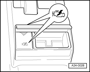
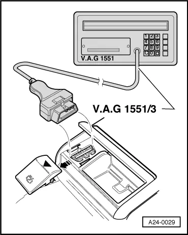
| Use the current flow diagram to check the wiring for the diagnostic connector. |
|
||
|
|||
|
|
| → If this display appears at the start of or during the program, faults have occurred and data exchange is no longer possible between the fault reader V.A.G 1551 and the operating and display unit -E87. |
|
||
|