
A4 Mk1
|
Removing and installing gearbox
Removing
|
 |
|
|
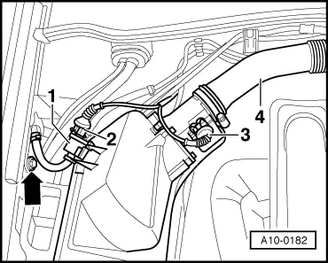
Vehicles with 4-cylinder normally aspirated engine:
|
 |
|
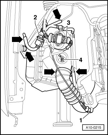
Note: Avoid excessive bending of the decoupling element at front exhaust pipe (max. 10o). Vehicles with 4-cylinder turbo engine:
|
 |
|
|
 |
|
|
Note: Avoid excessive bending of the decoupling element at front exhaust pipe (max. 10o). Vehicles with 6-cylinder engine:
|
 |
|
|
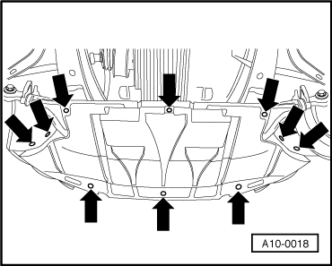
All models:
|
 |
|
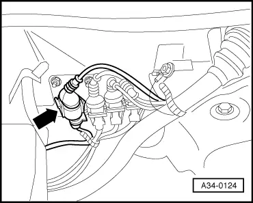
Vehicles with 4-cylinder engine: |
 |
|
|
 |
|
|
 |
|
|
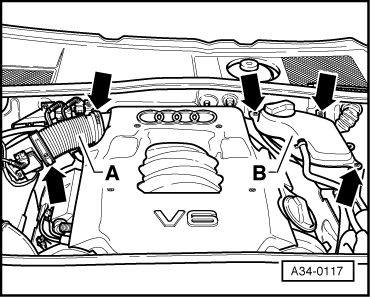
Vehicles with 6-cylinder engine:
=> 6-cylinder Engine (2-valve), Mechanics; Repair Group 26; Removing and installing exhaust system |
 |
|
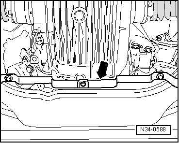
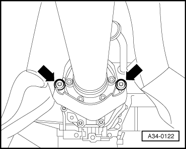
All models: |
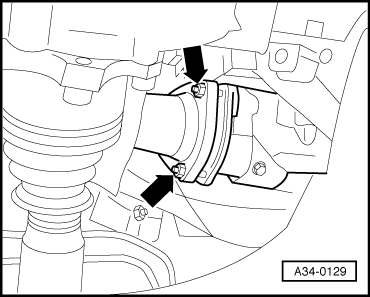
 |
|
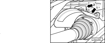
Note: Take care not to damage protective coating on drive shafts.
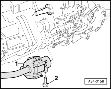
|
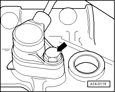
 |
|
=> Electrical system; Repair Group 27; Removing and installing starter Note: Starter cables do not need to be disconnected. Vehicles with standard-travel shift mechanism: |
 |
|
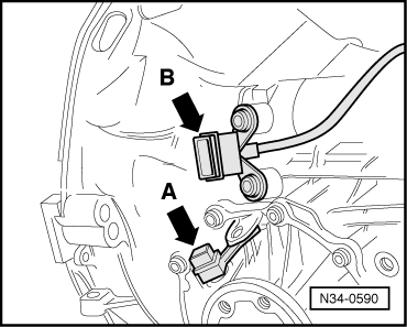
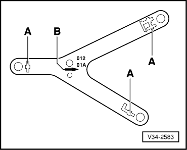
Vehicles with short-travel shift mechanism: |
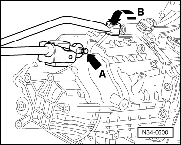 |
|
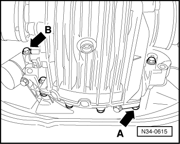
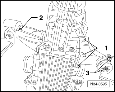
Note: Shown in illustration on manual gearbox 012. All models: |
 |
|
|
 |
|
|
 |
|
|
 |
|
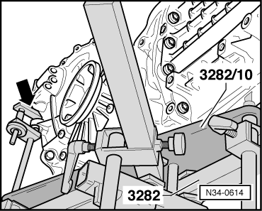
Notes:
|
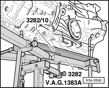 |
|
Note: If gearbox support 3282 is not available, gearbox can be removed and installed using gearbox lifter V.A.G 1383 A and universal support V.A.G 1359/2.
|
 |
|
Vehicles with 4-cylinder engine: |
 |
|
Vehicles with 6-cylinder engine: |
 |
|
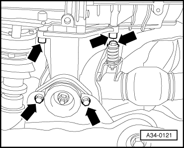
All models: |
 |
|
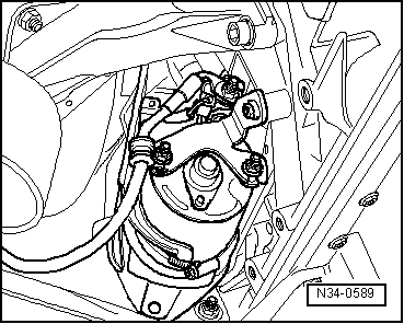
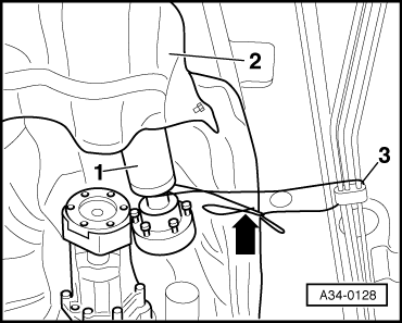
Note: When lowering gearbox ensure hydraulic pipe/hose to slave cylinder is not damaged. |
 |
|
Note: Do not depress clutch pedal after removing slave cylinder.
Note: When lowering gearbox ensure there is sufficient clearance to drive shafts. |