audi Workshop Repair Guides

Audi Workshop Service and Repair Manuals

Reinforcements from 08.98 > (as of gearbox build date 17 08 8) in the area of the 4th gear wheel > < Adjusting input shaft
5-Speed Manual Gearbox 01A (4WD)
Dismantling and assembling drive pinion and hollow shaft

Special tools, testers and auxiliary equipment required

  • ◆ Thrust plate VW 401
  • ◆ Thrust plate VW 402
  • ◆ Press tool VW 407
  • ◆ Press tool VW 411
  • ◆ Press tool VW 412
  • ◆ Tube VW 415 A
  • ◆ Tube VW 416 B
  • ◆ Tube VW 418 A
  • ◆ Thrust ring VW 429
  • ◆ Thrust plate VW 447 i
  • ◆ Thrust piece VW 454
  • ◆ Tube VW 519
  • ◆ Multi-purpose tool VW 771
  • ◆ Support 40-103
  • ◆ Tube 2010
  • ◆ Thrust pad 3062
  • ◆ Fitting tool 3128
  • ◆ Separating tool Kukko 17/2
  • ◆ Internal puller Kukko 21/1
 
N35-0201

Notes:

  • ◆ When installing new gears or the final drive set consult technical data .
  • ◆ Adjustments are required when replacing components marked 1) => adjustment overview, Page 39-44.
  • Gearbox housing
  • Shim "S3"
    • ◆ Adjustment overview
  • Outer race for double taper roller bearing 1)
    • ◆ Replace together with -Item 5-
    • ◆ Pulling out =>Fig.1
    • ◆ Pressing in => Fig.3
 
N35-0201
  • Pinion shaft 1)
    • ◆ Is mated with crown wheel, renew together as a set
    • ◆ Adjusting crown wheel and pinion shaft => Page 39-40
  • Inner race for double taper roller bearing 1)
    • ◆ Replace
    • ◆ Will be damaged during removal
    • ◆ Pressing off => Fig.2
    • ◆ Pressing on =>Fig.4
  • Circlip
    • ◆ If the double taper roller bearing hub is replaced re-determine thickness =>Fig.5
  • Needle bearing
    • ◆ For drive pinion in hollow shaft
    • ◆ Lubricate with MoS2-grease
 
N35-0201
  • Hollow shaft1)
    • ◆ From 08.98 ä Reinforcements => from Page 35-47
  • Needle roller bearing for 1st gear
  • Needle roller bearing for 1st gear
  • 1st speed sliding gear
  • Spring
    • ◆ Insert in 1st speed sliding gear => Fig.16
    • ◆ Allocation of spring to sliding gear

=> Parts List

  • Synchro-ring for 1st gear
    • ◆ Checking for wear => Fig.17
  • Synchro-hub for 1st and 2nd gear
    • ◆ Pressing off => Fig.14
    • ◆ Pressing on =>Fig.18
 
N35-0201
  • Circlip
    • ◆ Mark
    • ◆ Installation position => Fig.15 -Item 1-
    • ◆ If the synchro-hub is replaced re-determine thickness =>Fig.5
  • Needle roller bearing for 2nd gear
  • Locking collar, 1st and 2nd gear
    • ◆ Installation position => Fig.19
  • Synchro-ring for 2nd gear
    • ◆ Checking for wear => Fig.17
  • Spring
    • ◆ Insert in 2nd speed sliding gear => Fig.16
    • ◆ Allocation of spring to sliding gear

=> Parts List

  • 2nd gear sliding gear
 
N35-0201
  • Circlip
    • ◆ Mark
    • ◆ Installation position => Fig.15 - Item 2
  • 3rd gear wheel
    • ◆ Pressing off => Fig.13
    • ◆ Pressing on =>Fig.20
  • Circlip
    • ◆ Mark
    • ◆ Installation position => Fig.15 - Item 3
    • ◆ If the 3rd gear wheel is replaced re-determine thickness =>Fig.5
  • 4th gear wheel
    • ◆ Pressing off => Fig.12
    • ◆ Pressing on =>Fig.21
    • ◆ From 08.98 ä Reinforcements => from Page 35-47
  • Circlip
    • ◆ Mark
    • ◆ Installation position => Fig.15 -Item 4-
    • ◆ If the 4th gear wheel is replaced re-determine thickness =>Fig.5
    • ◆ From 08.98 ä Reinforcements => from Page 35-47
 
N35-0201
  • Needle bearing
    • ◆ From 08.98 ä Reinforcements => from Page 35-47
  • 5th speed sliding gear
    • ◆ From 08.98 ä Reinforcements => from Page 35-47
  • Spring
    • ◆ Insert in 5th speed sliding gear => Fig.16
    • ◆ Allocation of spring to sliding gear

=> Parts List

  • Synchro-ring for 5th gear
    • ◆ Checking for wear => Fig.17
  • Circlip
    • ◆ Mark
    • ◆ Installation position => Fig.15 - Item 5
  • 5th gear and reverse gear synchro-hub
    • ◆ Pressing off => Fig.11
    • ◆ Pressing on =>Fig.22
 
N35-0201
  • Circlip
    • ◆ Mark
    • ◆ Installation position => Fig.15 -Item 6-
    • ◆ If the synchro-hub is replaced re-determine thickness =>Fig.5
  • Needle bearing
    • ◆ For reverse gear
  • Locking collar for 5th gear and reverse gear
    • ◆ Installation position => Fig.23
  • Reverse gear synchro-ring
    • ◆ Checking for wear => Fig.17
  • Spring
    • ◆ Insert in reverse sliding gear => Fig.16
    • ◆ Allocation of spring to sliding gear

=> Parts List

 
N35-0201
  • Reverse sliding gear
  • Circlip
    • ◆ Mark
    • ◆ Installation position => Fig.15 -Item 7-
  • Inner race for small taper roller bearing 1)
    • ◆ Pressing off => Fig.9
    • ◆ Pressing on =>Fig.10
  • Bushing
    • ◆ To secure small taper roller bearing outer race
    • ◆ Pulling out =>Fig.6
    • ◆ Does not need to be fitted after the small taper roller bearing has been replaced.
 
N35-0201
  • Outer race for large taper roller bearing 1)
    • ◆ Pressing out =>Fig.7
    • ◆ Pressing in => Fig.8
  • Shim "S4"
    • ◆ Adjustment overview => Page 39-44
  • Ring
    • ◆ Holds rubber washer
    • ◆ Allocation

=> Parts List

  • Rubber washer
    • ◆ Compensates variations in length
    • ◆ Allocation

=> Parts List

  • Gearbox cover
 
N35-0056

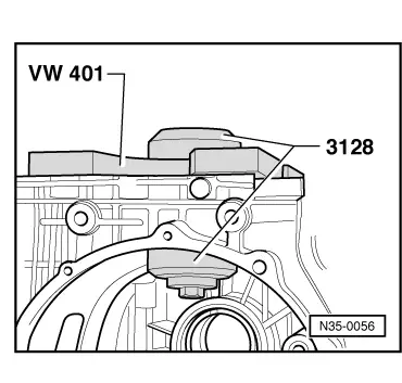
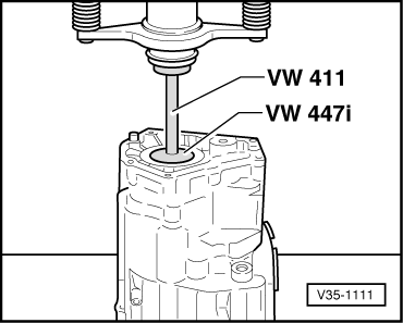
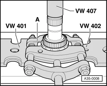
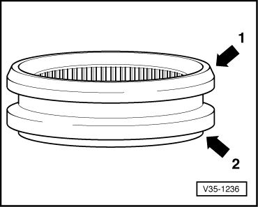
→ Fig.1    Pulling out outer race for double taper roller bearing

  • ‒ Remove differential => Page 39-18.
  • ‒ Place pressure piece of puller 3128 below the outer race.
  • ‒ Fit threaded part of puller 3128 with pressure plate VW 401 onto gearbox housing.

When tightening the bolt the outer race will be pulled out of the housing.

 
V35-1083

→ Fig.2    Pressing off inner race for double taper roller bearing

  • ‒ Remove circlip before pressing off.
  • ‒ The outer race -A- must be fitted to press off the inner race.

Note:

Inner race for double taper roller bearing will be destroyed when pressed off.

 
V35-1044

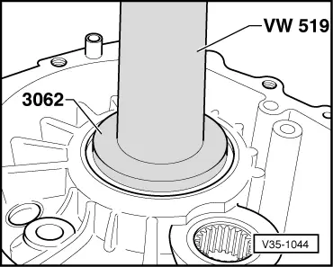
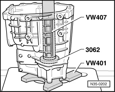
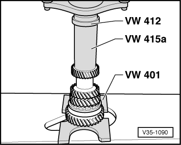
→ Fig.3    Pressing in outer race for double taper roller bearing

The smaller diameter of thrust pad VW 3062 faces outer race.

 
V35-1084

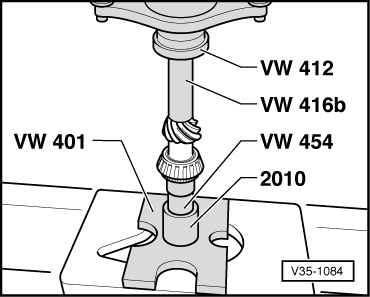
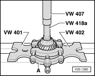
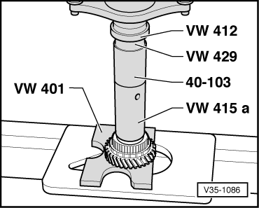
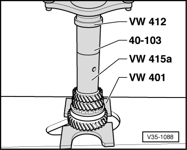
→ Fig.4    Pressing on inner race for double taper roller bearing

 
V35-1107

→ Fig.5    Determining thickness of circlip

  • ‒ Determine the thickest circlip that will just fit and install it.
  • ‒ The circlips for synchro-hubs, needle bearings and individual gear wheels should also be determined as shown for double taper roller bearing.
  • Available circlips and part numbers

=> Parts List

 
V34-2118

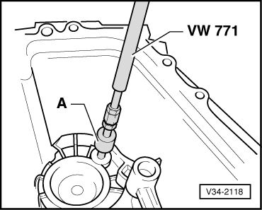
→ Fig.6    Pulling out securing bush for small taper roller bearing outer race

  •     A -    Internal puller 12 ... 14.5 mm, e.g. Kukko 21/1
 
V35-1111

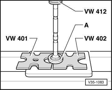
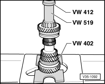
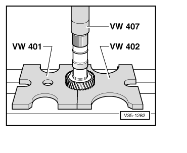
→ Fig.7    Pressing out outer race for taper roller bearing

  • ‒ Outer race is pressed out together with ring -Item 35-32.

 
N35-0202

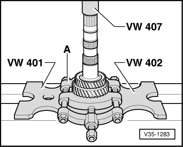
→ Fig.8    Pressing in outer race for taper roller bearing

 
V35-1280

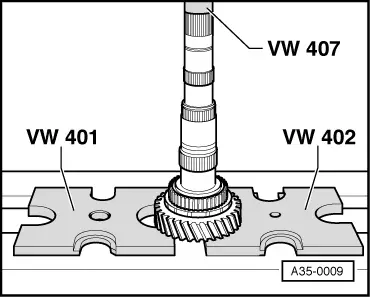
→ Fig.9    Pressing off inner race for taper roller bearing

  • ‒ Press off inner race with reverse gear sliding gear.
  •     A -    Separating device 22 ... 115 mm, e.g. Kukko 17/2

 
V35-1092

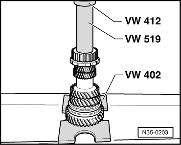
→ Fig.10    Pressing on inner race for taper roller bearing

  • ‒ Fit circlip before pressing on inner race.
 
A35-0008

→ Fig.11    Pressing off 5th gear and reverse gear synchro hub

  • ‒ Remove circlip before pressing off.
  • ‒ Press off synchro hub with 5th speed sliding gear.
  •     A -    Separating device 22 ... 115 mm, e.g. Kukko 17/2

 
V35-1282

→ Fig.12    Pressing off 4th gear wheel

  • ‒ Remove circlip before pressing off.
 
V35-1283

→ Fig.13    Pressing off 3rd gear wheel

  • ‒ Remove circlip before pressing off.
  • ‒ Press 3rd gear wheel off with 2nd speed sliding gear.
  •     A -    Separating device 22 ... 115 mm, e.g. Kukko 17/2

 
A35-0009

→ Fig.14    Pressing off synchro hub for 1st and 2nd gear

  • ‒ Remove circlip before pressing off.
  • ‒ Press off synchro hub with 1st speed sliding gear.
 
V35-1104

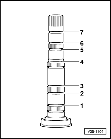
→ Fig.15    Installation position of circlips

  • ‒ The circlips for the synchro-hubs, needle roller bearings and individual gear wheels should also be determined as shown in Fig.5.
  • ◆ Circlip -1- secures the 1st and 2nd gear synchro hub.
  • Identification: blue colour.

Circlip thickness (mm)

1.90

1.96

2.02

1.93

1.99

  • ◆ Circlip -2- secures the needle roller bearing for 2nd speed sliding gear.
  • Thickness: 2.50 mm. Identification: blue colour.
  • ◆ Circlip -3- secures the 3rd gear wheel.

Circlip thickness (mm)

1.90

1.98

2.06

1.94

2.02

 
V35-1104
  • ◆ → Circlip -4- secures the 4th gear wheel.

Circlip thickness (mm)

1.86

1.94

1.90

1.98

  • ◆ Circlip -5- secures the needle roller bearing for 5th speed sliding gear.
  • Thickness: 2.00 mm. Identification: brown colour.
  • ◆ Circlip -6- secures the synchro-hub for 5th gear and reverse gear.
  • Identification: blue colour.

Circlip thickness (mm)

1.90

1.96

2.02

1.93

1.99

2.05

  • ◆ Circlip -7- secures the needle roller bearing for sliding gear for reverse gear.
  • Thickness: 2.50 mm.
  • ‒ Determine circlips according to table: Part numbers

=> Parts List

 
V35-1036

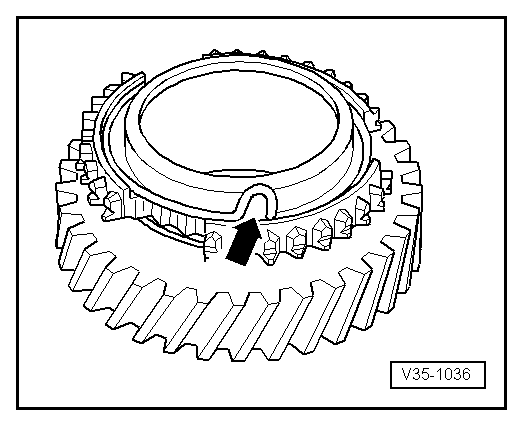
→ Fig.16    Inserting spring in sliding gear

The bent end of the spring (arrow) must be hooked in the hole in the sliding gear.

 
V35-1037

→ Fig.17    Checking synchro-ring for wear

  • ‒ Press synchro-ring into locking collar and measure gap -a- with a feeler gauge at positions -A-, -B- and -C-.
  • ‒ Add the measured values and divide by 3.

The calculated value must not be less than 0.5 mm.

 
V35-1086

→ Fig.18    Pressing on synchro-hub for 1st and 2nd gear

  • ◆ Installation position:
  • High inside collar faces 2nd gear

 
V35-1236

→ Fig.19    Installation position of locking collar for 1st and 2nd gear

  • ◆ Installation position:
  • Bevelled edges -arrow 1- faces 2nd gear
  • Shoulder -arrow 2- faces 1st gear
 
V35-1088

→ Fig.20    Pressing on 3rd gear wheel

  • ◆ Installation position:
  • Groove on gear wheel faces 4th gear

 
V35-1090

→ Fig.21    Pressing on 4th gear wheel

  • ◆ Installation position:
  • High inside collar faces 3rd gear
 
N35-0203

→ Fig.22    Pressing on 5th gear and reverse gear synchro hub

  • ◆ Installation position:
  • High inside collar faces 5th gear

 
A35-0003

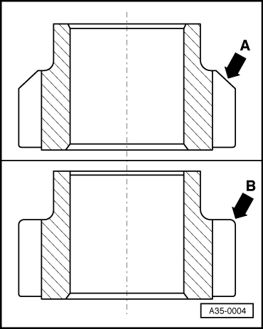
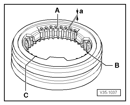
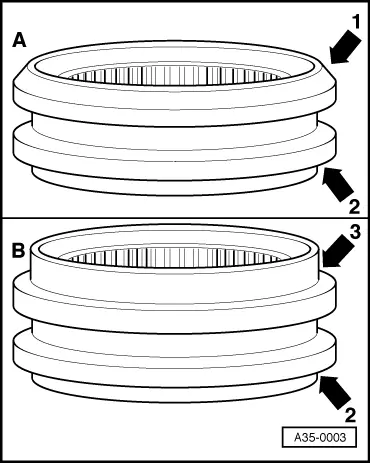
→ Fig.23    Installation position of locking collar for 5th and reverse gear

Only locking collars with chamfered edges -A- as well as with large shoulders -B- are fitted.

  • ◆ Make sure locking collar is correct version for reverse gear wheel => Fig.24
  • ◆ Installation position:
  • Bevelled edges -arrow 1- faces reverse gear
  • Small shoulder -arrow 2- faces 5th gear
  • Large shoulder -arrow 3- faces reverse gear
 
A35-0004

→ Fig.24    Selecting correct locking collar for reverse gear wheel

A

Reverse gear wheel with chamfered edge

Both types of locking collar can be fitted (with chamfered edge or large shoulder).

B

Reverse gear wheel without chamfered edge.

Install only locking collar with large shoulder, do not use locking collar with chamfered edge.

Reinforcements from 08.98 > (as of gearbox build date 17 08 8) in the area of the 4th gear wheel > < Adjusting input shaft