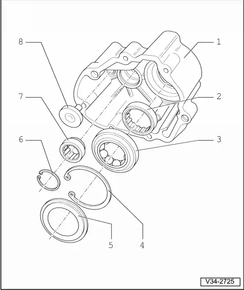
audi Workshop Repair Guides

Audi Workshop Service and Repair Manuals

Servicing bearing plate > < Installing
5 & 6-Speed manual gearbox 01E, Front-wheel drive
Servicing end cover
Servicing end cover
 
V34-2725

Note:

General repair instructions .

  • End cover
    • ◆ If renewed, re-determine thickness of circlip -item 4-
  • Cylinder roller bearing for input shaft
    • ◆ Pressing out => Fig.1
    • ◆ Pressing in flush => Fig.2
  • Four-point bearing for input shaft
    • ◆ Removing =>Fig.3
    • ◆ Installing =>Fig.4
    • ◆ If renewed, re-determine thickness of circlip -item 4-
 
V34-2725
  • Circlip
    • ◆ Re-determining thickness
    • ◆ Installing =>Fig.4
  • Baffle plate
    • ◆ Always renew
    • ◆ Removing =>Fig.3
    • ◆ Installing and peening in position when renewing four-point bearing for input shaft => Fig.5
    • ◆ Installing and peening in position when replacing end cover => Fig.6
  • Circlip
 
V34-2725
  • Roller sleeve for drive pinion
    • ◆ Becomes damaged when removed
    • ◆ Always renew
    • ◆ Removing => Fig. 7
    • ◆ Driving in => Fig.8
    • ◆ Installation position => Fig. 9
  • Magnet
    • ◆ Drive in, for example with press tool VW 408 A
 
V35-1336

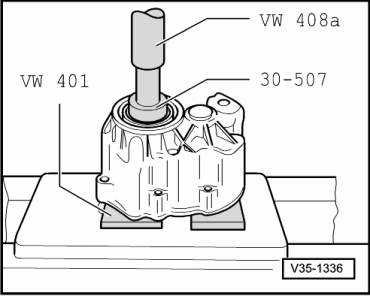
→ Fig.1    Pressing cylinder roller bearing for input shaft out of end cover

 
V35-1337

→ Fig.2    Pressing cylinder roller bearing for input shaft into end cover

  • ◆ Place thrust plate 30-205 onto bearing with recessed side facing upwards.

Note:

To press in the cylinder roller bearing, place thrust pad 3062 under the seating collar for the cylinder roller bearing on the end cover.

 
V35-1339

→ Fig.3    Removing four-point bearing for input shaft from end cover

  • ‒ Position screwdriver as illustrated, drive into baffle plate -arrow- and lever out.
  • ‒ Remove circlip.
  • ‒ Take out bearing, remove peening indentations if necessary.

 
V35-1338

→ Fig.4    Installing four-point bearing for input shaft in end cover

Installation position of circlip:

  • ◆ Ends of circlip -arrows- towards roller sleeve for drive pinion

Note:

The thickness of the circlip must be re-determined if the bearing or the end cover are replaced.

  • ‒ Determining thickness of circlip for four-point bearing for input shaft:
    • ‒ Press outer race of four-point bearing onto stop.
    • ‒ Determine the thickest circlip that can still just be fitted.
    • ‒ Axial play: max. 0.08 mm
    • ‒ Determine circlip from table. Part numbers

=> Parts catalogue

Circlips available

Circlip thickness (mm)

2.55

2.65

2.60

2.70

  • ‒ Fit circlip.
 
V35-1340

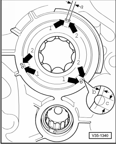
→ Fig.5    Peening baffle plate in position when renewing four-point bearing for input shaft

  • ‒ Use a blunt punch with a ball shaped end (ball diameter 5 mm) to peen in position.
  • ‒ Insert baffle plate.
  • ‒ First peen at points marked with -arrows 1-.
  • ‒ Then peen at points marked with arrows 2- at distance -a- from first position.
    • ‒ Dimension a = 5 mm
  • ‒ Observe position and diameterof peening positions:
    • ‒ Dimension b = 2 mm
    • ‒ Dimension c = 3 mm
 
V35-1351

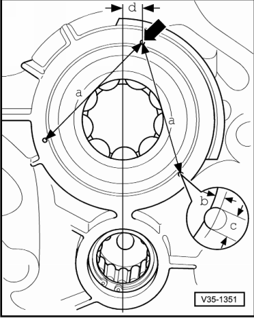
→ Fig.6    Peening baffle plate in position when renewing end cover

  • ‒ Use a blunt punch with a ball shaped end (ball diameter 5 mm) to peen in position.
  • ‒ Insert baffle plate.
  • ‒ Peen in first peening point -arrow- at distance -d- from the centre line of the two shafts.
    • ‒ Dimension d = 10 mm
  • ‒ Observe position and diameter of peening positions.
    • ‒ Dimension b = 2 mm
    • ‒ Dimension c = 3 mm
  • ‒ Peen in second and third peening points in same manner at distance -a-.
    • ‒ Dimension a = 70 mm
 
V34-2639

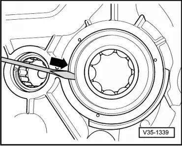
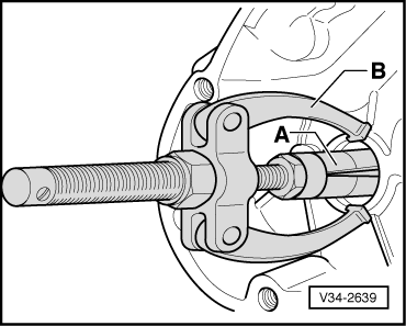
→ Fig.7    Pulling roller sleeve for drive pinion out of end cover

  • ‒ Remove circlip.
  •     A -    Internal puller 22 ... 28 mm, e.g. Kukko 21/4
  •     B -    Counterhold, e.g. Kukko 22/1

 
V34-2726

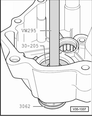
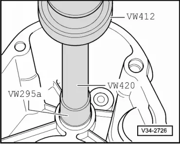
→ Fig.8    Driving roller sleeve for drive pinion into end cover

  • ‒ Note installation position => Fig.9.
 
V34-2727

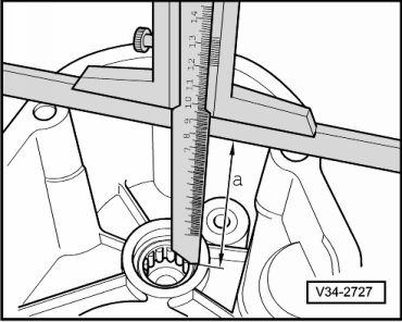
→ Fig.9    Installation position of roller sleeve for drive pinion

  • ◆ Dimension a = 98.6 mm

Servicing bearing plate > < Installing