
A4 Mk1
|
Removal on vehicles with V6 bi-turbo engine (S4, RS4)
Removal on vehicles with V6 bi-turbo engine (S4, RS4)
|
 |
|
|
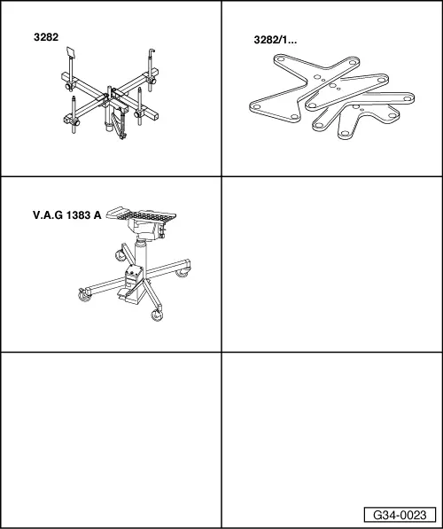
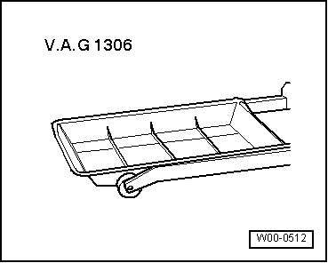
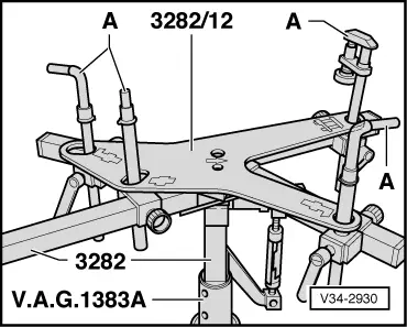
Special tools and workshop equipment required
|
 |
|
|
Special tools, testers and other items required
Note: All cable ties unfastened or cut open on removal are to be re-attached in same position on installation. Attention:
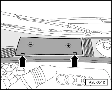
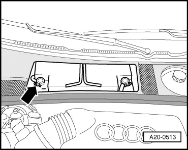
Heed appropriate instructions for battery disconnection. =>Electrical System; Repair Group 27 |
 |
|
|
 |
|
|
 |
|
|
 |
|
|
 |
|
Note: Take care not to damage surface protection of drive shafts. |
 |
|
|
 |
|
|
 |
|
|
 |
|
|
 |
|
|
 |
|
|
 |
|
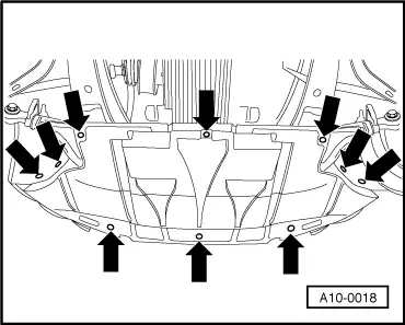
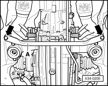
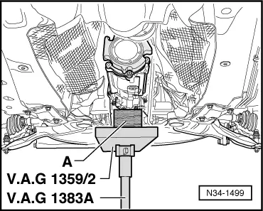
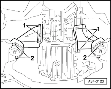
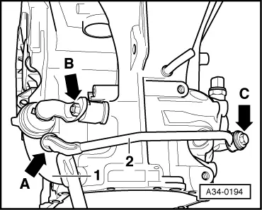
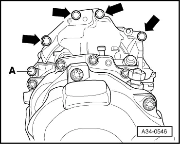
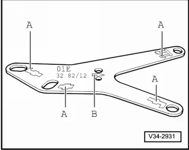
A - Wooden block |
 |
|
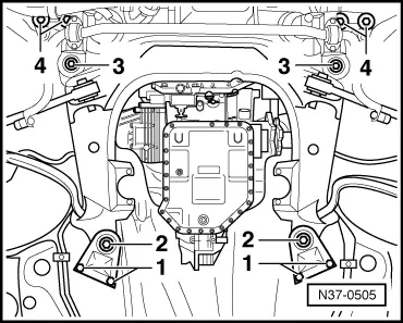
Note: Bolts -3- and -4- are not to be screwed out, as otherwise wheel alignment would have to be performed. |
 |
|
|
 |
|
|
|
|
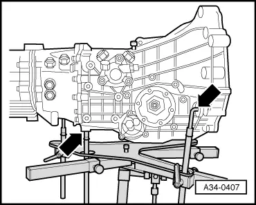
Note: Take care not to damage selector rods on further raising gearbox. |
 |
|
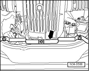
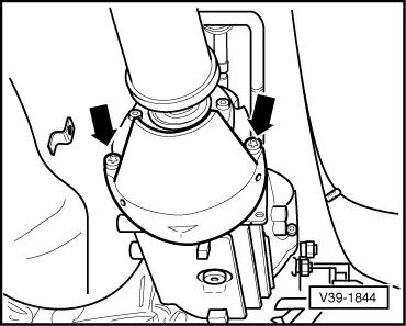
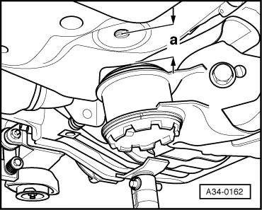
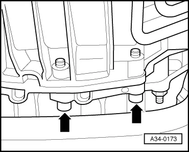
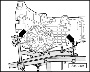
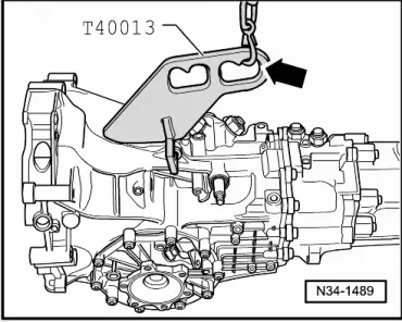
Note: To permit tightening of the two bolts -arrows- with a torque wrench following gearbox installation, the two hexagon socket-head bolts M10x60 must be replaced with new hexagon bolts M10x55, part no. N 104 684 01.
|
 |
|
|
 |
|
|
 |
|
|
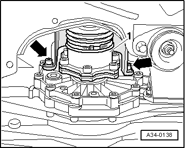
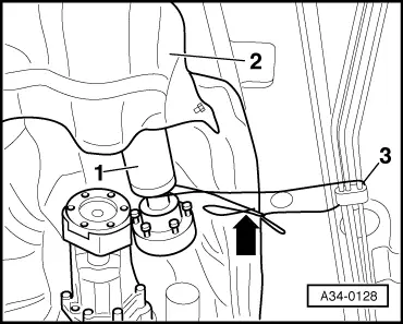
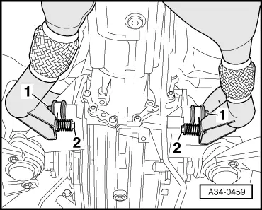
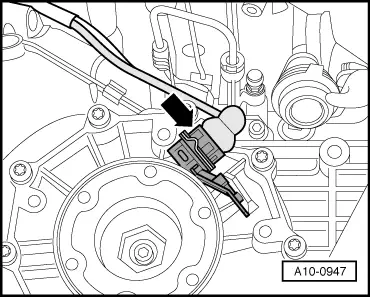
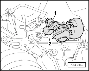
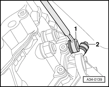
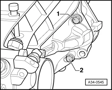
Important note on subsequent operations: → When removing shift mechanism (up to approx. 11.00), never detach ball end -arrow A- of connecting rod -2- from selector rod -1-. Detaching would destroy ball end. |
 |
|
|
 |
|
|
Version with push rod on side:
Version with push rod at top: |
 |
|
Note: Packing plates may have been fitted between gearbox and push rod. If this is the case, they must be inserted again on assembly. All models:
|
 |
|
|
 |
|
|
 |
|
|
Notes:
=> Electrical System; Repair Group 27; Removing and installing starter |
 |
|
|
 |
|
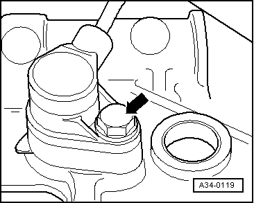
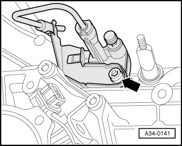
Note: Leave connecting bolt -A- screwed in to hold in position. |
 |
|
|
Notes:
|
 |
|
|
 |
|
|
 |
|
|
 |
|
|
 |
|
Note: Do not press clutch pedal after removing slave cylinder. |
 |
|
|
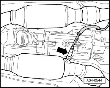
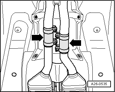
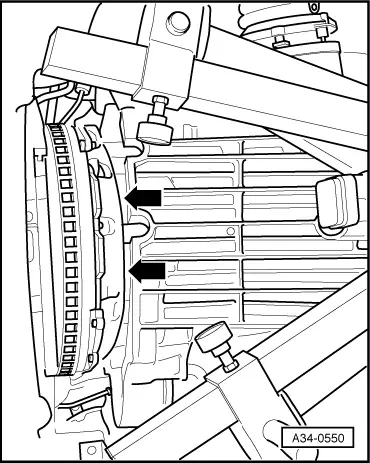
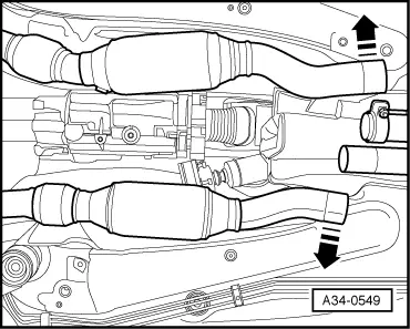
Note: Take care not to over-deflectdecoupling element (flexible pipe connection) at front exhaust pipe. Catalytic converter must notbe offset by more than 10 °with respect to front exhaust pipe as otherwise decoupling element would be damaged.
Note: On lowering, ensure clearance with respect to drive shafts. |
 |
|
|
Gearbox transportation
|