|
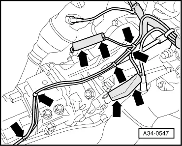
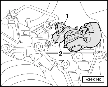
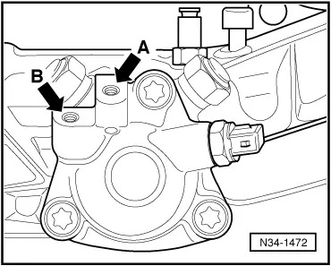
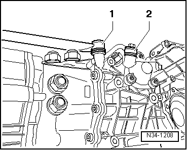
Removal on vehicles with V6 bi-turbo engine (S4, RS4)
Fitting gearbox on vehicles with V6 bi-turbo engine (S4, RS4)
Install in reverse order, paying attention to the following:
Notes:
-
◆ Replace self-locking nuts and bolts when performing assembly work.
-
◆ Replace bolts tightened to torque as well as sealing rings and gaskets.
-
◆ Secure all hose connections with standard hose clamps.
=> Parts List
-
◆ All cable ties unfastened or cut open on removal are to be re-attached in same position on installation.
-
◆ Before installing gearbox, tie wiring to one side so that it cannot be trapped between engine and gearbox.
-
◆ Check whether dowel sleeves for centring engine/gearbox have been fitted in engine flange and insert if necessary .
-
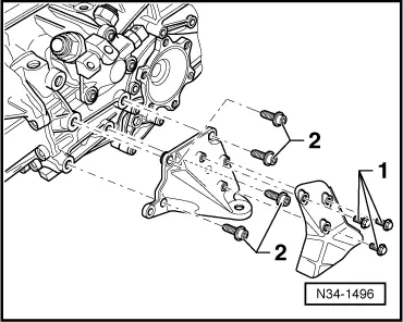
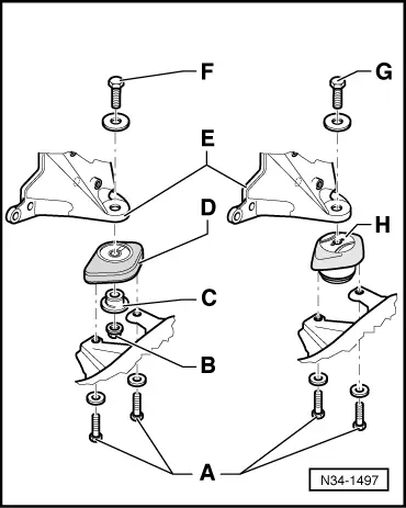
◆ If gearbox is replaced, transfer gearbox supports with gearbox mounting. Tightening torques => Page 34-142.
|