audi Workshop Repair Guides

Audi Workshop Service and Repair Manuals

Removal on vehicles with V6 bi-turbo engine (S4, RS4) > < Removal on vehicles with V6 TDI engine
6-speed manual gearbox 01E Four-wheel drive
Removing and installing gearbox
Installing gearbox on vehicles with 4 and 6-cyl. TDI engine

Install in reverse order, paying attention to the following:

Notes:

  • ◆ Replace self-locking nuts and bolts when performing assembly work.
  • ◆ Replace bolts tightened to torque as well as sealing rings and gaskets.
  • ◆ All cable ties unfastened or cut open on removal are to be re-attached in same position on installation.
  • ◆ Before installing gearbox, tie wiring to one side so that it cannot be trapped between engine and gearbox.
  • ◆ Check whether dowel sleeves for centring engine/gearbox have been fitted in engine flange and insert if necessary .
  • ◆ If gearbox is replaced, transfer gearbox supports with gearbox mounting. Tightening torques => Page 34-108.
  • ◆ Tightening torques only apply to slightly greased, oiled, phosphated or blackened nuts and bolts.
  • ◆ Additional lubricants, such as engine or gear oil are permitted, however not lubricants which contain graphite.
  • ◆ Tolerance for tightening torques ±15%
 
A30-0037
  • ‒ → Before installing slave cylinder in gearbox housing, area -a- of boot must be coated with lithium grease G 052 150 A2.
  • ‒ Prior to assembly, always use thread tap to remove remnants of locking fluid from tapped holes in flange shaft of manual gearbox for propshaft.
  • ‒ Clean input shaft splines and - in the case of used clutch plates - hub splines, remove corrosion and apply extremely thin layer of grease G 000 100 to splines. Do not grease guide sleeve.
  • ‒ Check clutch release bearing for wear and replace if necessary.

 
N30-0285
  • ‒ → If plastic ring of release bearing is loose, bond it back onto bearing race with adhesive AMV 195 KD1 01.
    • ‒ Three square lugs -arrows- of the plastic ring engage in the recesses of the bearing race.
    • ‒ Release bearing must be replaced in the event of scoring deeper than 0.5 mm.
 
A34-0116
  • ‒ Apply thin coat of copper grease, e.g. Z 381 351 TE, to contact surface for plunger at clutch release lever.

Vehicles with V6 TDI engine:

  • ‒ → Before installing gearbox with V6 TDI engine, check that brace -B- is still moved to one side -arrow direction-.

All models:

  • ‒ Before installing gearbox, tie wiring to one side so that it cannot be trapped between engine and gearbox.
 
A34-0141
  • ‒ → Raise gearbox such that clutch slave cylinder can be installed with holder for hose/pipe assembly (arrow).
  • ‒ Insert gearbox.
  • ‒ Tighten engine/gearbox connecting bolts to torque => Page 34-106 onwards.
  • ‒ Fit and secure starter.

=> Electrical System; Repair Group 27; Removing and installing starter

 
A34-0140
  • ‒ → Press selector lever on gearbox -2- onto gearbox selector shaft.
  • ‒ Tighten nut -1- to 23 Nm.

 
N34-1472

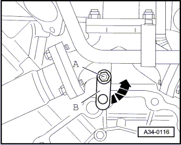
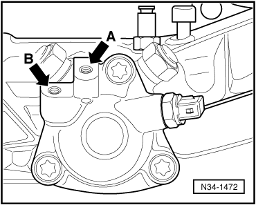
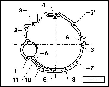
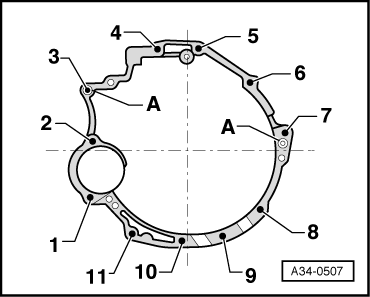
Note:

→ Cover for selector shaft is provided with an additional tapped hole

-arrow A- as attachment point for newer connecting rod versions.

Distinguishing feature => Page 34-35

 
N34-1208
  • ‒ → Screw (40 Nm) push rod -1- to gearbox with washers if applicable.
  • ‒ Screw (23 Nm) connecting rod of selector rod -2- to right side of gearbox.
  • ‒ Attach reversing light connector.
  • ‒ Attach connector of speedometer sender.

 
A34-0119
  • ‒ → Attach engine speed sender -G28- to gearbox housing -arrow-.
 
A34-0123
  • ‒ → Screw right and left gearbox support complete with bonded rubber bush to gearbox and subframe (bolts -1- and -2-). Tightening torques => Page 34-108.

 
A34-0540
  • ‒ → Secure subframe with bolts -2- and -3-.

=> Running Gear, Front-wheel Drive and Four-wheel Drive; Repair Group 40; Removing and installing subframe

  • ‒ If applicable, screw cross member -A- to subframe.

=> Running Gear, Front-wheel Drive and Four-wheel Drive; Repair Group 40; Removing and installing subframe; Removing and installing lower cross member

 
A34-0138
  • ‒ → Attach drive shafts -1- to flange shafts.

=> Running Gear, Front-wheel Drive and Four-wheel Drive; Repair Group 40; Removing and installing drive shaft

  • ‒ Attach shield/drive shaft on right and left -arrows-. Third bolt is not shown.
  • ‒ Install oil pipes => Page 34-145.
  • ‒ Replace seal at front of propshaft => Page 39-85.
  • ‒ Bolt on propshaft => Page39-91.
  • ‒ Assemble exhaust system and perform stress-free alignment.

=> Engine, Mechanics; Repair Group 26; Removing and installing exhaust system components

  • ‒ Check and if necessary adjust setting of selector rod and push rod => Page 34-16.
  • ‒ Check gear oil level in manual gearbox => Page 34-143.
  • ‒ Heed appropriate instructions for battery connection.

=> Electrical System; Repair Group 27

  • ‒ After connecting battery, enter radio anti-theft code.

=> Radio operating instructions

  • ‒ Use electric window lifters to completely close door windows.
  • ‒ Then actuate all window lifter switches again for at least 1 second in "close" position to activate automatic one-touch function.
  • ‒ Set clock to correct time.
 
A37-0075

Tightening torques

→ Vehicles with 4-cyl. TDI engine:

Item

Bolt

Nm

1, 3, 4

M12 x 75

65

2, 6

M12 x 90

65

5, 11

M12 x 110

65

7

M10 x 50

45

8, 9, 10

M10 x 45

45

A: Dowel sleeves for centring

 
A34-0507

→ Vehicles with V6 TDI engine:

Item

Bolt

Nm

1, 2

M12 x 110

65

3, 4

M12 x 67

65

5, 7

M12 x 80

65

6

M12 x 90

65

8

M10 x 50

45

9, 10, 11

M10 x 45

45

A: Dowel sleeves for centring

    1)    Bolt not fitted on all versions

Component

Nm

Clutch slave cylinder to gearbox

23 1)

Engine speed sender -G28

10

Push rod to gearbox

40

Selector rod to gearbox

23

Connecting rod for selector rod to gearbox


23

Heat shields over drive shafts to gearbox


25

Holder for noise insulation to subframe

10

Heat shield for propshaft to cover for Torsen differential


25

Cross member for floor

M8

22

to body

M10

45

    1)    Always replace bolts

 
N34-1496

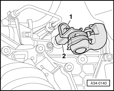
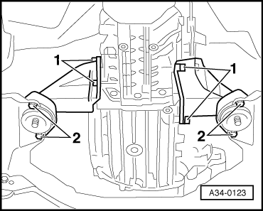
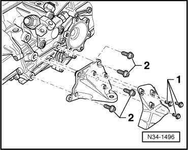
→ Right and left gearbox support to gearbox

Bolts -1-

10 Nm

Right and left gearbox support to gearbox


40

 
N34-1497

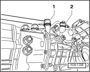
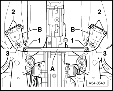
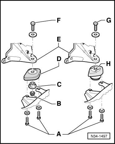
→ Right and left gearbox mounting to gearbox support/subframe

Bolts -A-

27 Nm

Nut -B- to bolt -F-

50 Nm

Bolt -G-1)

50 Nm

    1)    Bolt -G- is screwed directly into gearbox mounting -H-. Items -B- and -C- not applicable.

Removal on vehicles with V6 bi-turbo engine (S4, RS4) > < Removal on vehicles with V6 TDI engine