
A4 Mk1
|
Servicing shift mechanism
Removing and installing shift mechanism
|
 |
|
|
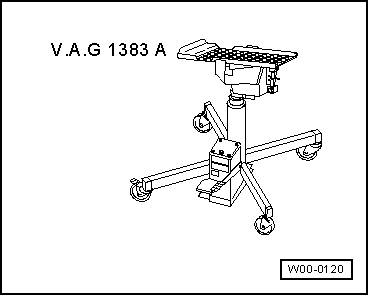
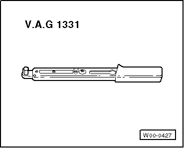
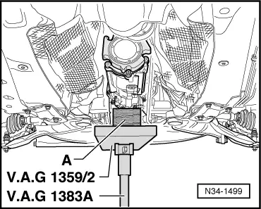
Special tools and workshop equipment required
|
 |
|
Removing |
 |
|
|
 |
|
|
 |
|
|
 |
|
|
 |
|
|
 |
|
|
 |
|
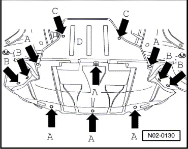
A - Wooden block |
 |
|
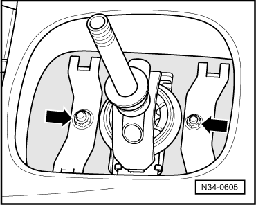
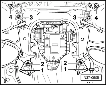
Note: Bolts -3- and -4- are not to be screwed out, as otherwise wheel alignment would have to be performed. |
 |
|
|
 |
|
|
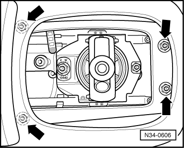
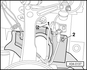
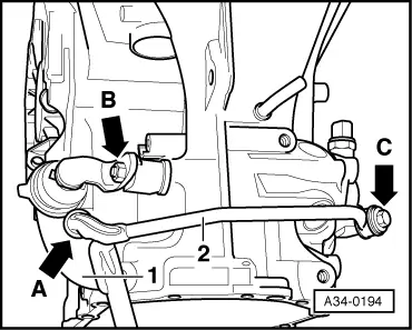
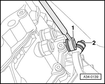
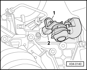
Important note on subsequent operations: → When removing shift mechanism, never detach ball end -arrow A- of connecting rod -2- from selector rod -1-. Detaching would destroy ball end. |
 |
|
|
 |
||||||||||||||||||
Installing Install in reverse order, paying attention to the following:
=> Running Gear, Front-wheel Drive and Four-wheel Drive; Repair Group 40
=> Running Gear, Front-wheel Drive and Four-wheel Drive; Repair Group 40
=> Engine, Mechanics; Repair Group 26
Tightening torques
| ||||||||||||||||||