
A4 Mk1
|
Electrical test
Electrical test
|
 |
|
|
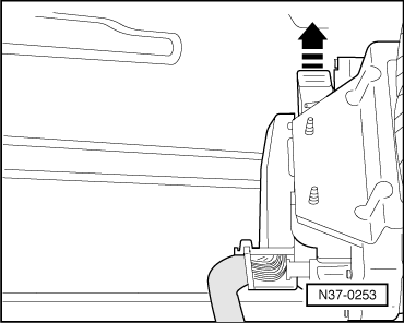
Note:
Control unit is located in front of right-hand seat under cover in footwell, Fig.1.
|
 |
|
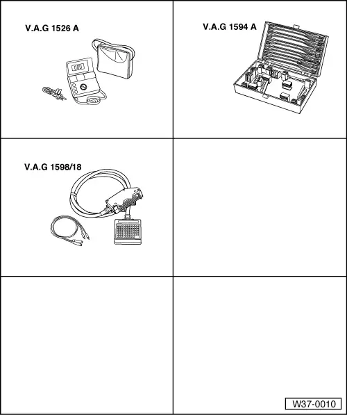
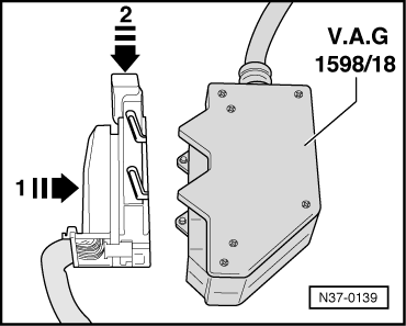
Using test box V.A.G 1598/18 the wiring can be checked according to current flow diagram. |
 |
|||||||||||||||||||||||||||||||||||||||||||||||||||||||||||||||||||||||||||||||||||||||||||||||||||||||||||||||||||||||||||||||||||||||||||||||||||||||||||||||||||||||||||||||||
|
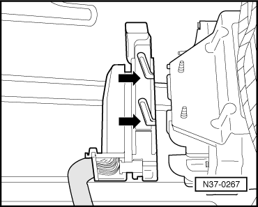
After electrical checks
When fitting ensure that the guides (arrows) are engaged on control unit pins. Multi-pin connector (68 pin) on control unit -J217- (sockets on V.A.G 1598/18)
1) Signal (contact 41) directed via engine control unit to gearbox control unit and can only be checked in "Reading measured value block" => Page 01-66. List of test steps (multi-pin connector with 68 pins) Only perform test steps for the relevant component as listed in fault finding table and read measured value block.
|