|
Electrical test
Test table
|
|
|---|
|
Switch to voltage measuring range V =
|
|
Test step
|
V.A.G 1598/18 sockets
|
Component tested
|
▪ Test conditions
- Additional steps
|
Specification
|
Fault rectification if readout does not match specification
|
|
1
|
23 + 1
|
Supply voltage from control unit -J217-
|
▪ Ignition switched on
|
approx.
battery
voltage
|
- Check wiring according to current flow diagram
Check wiring from contact 1 to earth
Check wiring from contact 23 to terminal 15, central electrics
|
|
2
|
29 + 15
|
Selector lever lock solenoid -N110-
|
▪ Ignition switched on
▪ Brake pedal not
▪ depressed
|
approx.
battery
voltage
|
- Check wiring according to current flow diagram
Perform test step 3
|
|
|
|
|
- Brake pedal depressed
|
0.2 V
|
- Renew selector lever lock solenoid
|
|
|
|---|
|
Switch to voltage measuring range V =
|
|
Test step
|
V.A.G 1598/18 sockets
|
Component tested
|
▪ Test conditions
- Additional steps
|
Specification
|
Fault rectification if readout does not match specification
|
|
3
|
15 + 1
|
Brake light switch -F-
|
▪ Ignition switched on
▪ Brake pedal not
▪ depressed
|
0 V
|
- Check wiring according to current flow diagram
Renew and adjust brake light switch -F-
|
|
|
|
|
- Brake pedal depressed
|
approx.
battery
voltage
|
=> Running Gear, Front-Wheel Drive; Repair Group 46; Brake mechanics, Servicing pedal cluster
|
|
4
|
60 + 1
|
Supply voltage for cruise control
system
|
▪ Ignition switched on
|
approx.
battery
voltage
|
- Check wiring according to current flow diagram
Check wire from contact 1 to earth
Check wire from contact 60 to terminal 15 on relay plate
Check fuse for cruise control system
=> Current flow diagrams, Electrical fault finding and Fitting locations
|
|
Switch to resistance measuring range ω
|
|
Test step
|
V.A.G 1598/18 sockets
|
Component tested
|
▪ Test conditions
- Additional steps
|
Specification
|
Fault rectification if readout does not match specification
|
|
5
|
63 + 1
63 + 23
40 + 1
40 + 23
62 + 1
62 + 23
18 + 1
18 + 23
|
Multi-function switch -F125
|
▪ Ignition switched off
▪ Multi-function switch
▪ -F125 and starter
▪ inhibitor and reversing light relay -J226
▪ disconnected
▪ Fuse for power supply of multi-function switch -F125 disconnected
|
infinite
ω
|
- Check plug connector on multi-function switch -F125 for contact corrosion; renew if necessary
Check wiring according to current flow diagram
If test readings match specifications in this electrical test, but the display readout in the corresponding measured value
|
|
|
63 + 1 1)
40 + 2 1)
|
|
|
|
≤ 1.5 ω
|
block does not match the
specification:
|
|
continued
▼
|
62 + 6 1)
18 + 5 1)
|
|
|
|
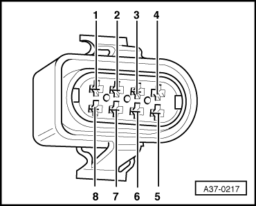
- Renew multi-function switch -F125 , Fig. 8
|
1) Contact on connector for multi-function switch -F125. For contact assignment => see Fig.01-113.
2) Either of the following types of multi-function switch -F125 may be fitted:
- mechanical switch, Part No. 095 919 823 B or.
- electronic switch, Part No. 095 919 823 F (phased in from gearbox code 29 11 5 onwards).
Identification: Part No. is on top of switch housing. If necessary, remove switch.
If fitting a new switch either type may be installed.
|
Switch to voltage measuring range V =
|
|
Test step
|
V.A.G 1598/18 sockets
|
Component tested
|
▪ Test conditions
- Additional steps
|
Specification
|
Fault rectification if readout does not match specification
|
|
5
|
29 + 1
1 + 7 1)
18 + 1
|
Multi-function switch -F125
|
▪ Ignition switched on
|
approx.
battery
voltage
|
- Check plug connector on multi-function switch -F125 for contact corrosion; renew if necessary
Test wiring according to current flow diagram
If test readings match specifications in this electrical test, but the display readout in the corresponding measured value block does not match the specification:
Renew multi-function switch -F125 => Page 01-20, Fig. 8
|
1) Contact on connector for multi-function switch -F125. For contact assignment => see Fig.01-113.
2) Either of the following types of multi-function switch -F125 may be fitted:
- mechanical switch, Part No. 095 919 823 B or.
- electronic switch, Part No. 095 919 823 F (phased in from gearbox code 29 11 5 onwards).
Identification: Part No. is on top of switch housing. If necessary, remove switch.
If fitting a new switch either type may be installed.
|