audi Workshop Repair Guides

Audi Workshop Service and Repair Manuals

Performing self-diagnosis > < Technical data of self-diagnosis
Automatic gearbox 01N Self-diagnosis
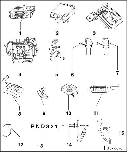
Locations of electrical/electronic components
 
A37-0076
  • Automatic gearbox control unit -J217-
    • ◆ Location => Fig.01-15
    • ◆ Removing => Fig. 01-15
    • ◆ Installing => Fig. 01-16
    • ◆ Control units are checked by self-diagnosis => Carrying out self-diagnosis, Page 01-27
  • Engine control unit
    • ◆ Location => Fig. 01-17

Note:

If engine or gearbox control units are replaced, the system must be brought to basic setting , Initiating basic setting.

 
A37-0076
  • Diagnosis connection
    • ◆ Location => Fig. 01-17
  • Valve body
    • ◆ Location => Fig. 01-18
    • ◆ The solenoid valves -N88-, -N89-, -N90-, -N91-, -N92-, -N93- and -N94- are attached to the valve body
    • ◆ The gearbox oil temperature sender (ATF) -G93 is integrated in the conductor strip (to solenoid valves); removing and installing=>Fig.7
    • ◆ Components are checked by self-diagnosis
  • Multi-function switch -F125-
    • ◆ Location and removing and installing =>Fig. 01-20
    • ◆ Checked by self-diagnosis
 
A37-0076
  • Gearbox speed sender -G38-
    • ◆ Location and removing and installing =>Fig. 01-21
    • ◆ Checked by self-diagnosis
    • ◆ Functioning is impaired by dirt; clean if necessary
  • Road speed sender -G68-
    • ◆ Location and removing and installing =>Fig. 01-21
    • ◆ Checked by self-diagnosis
    • ◆ Functioning is impaired by dirt; clean if necessary

Do not interchange connectors for senders -G38- and -G68-

 
A37-0076
  • Shift mechanism
    • ◆ Repairing shift mechanism

=> Automatic Gearbox 01N; Repair Group 37; Repairing shift mechanism

  • Solenoid for selector lever lock
    -N110-
    • ◆ Location => Fig. 01-22
    • ◆ Can be checked electrically
      => page 01-66
 
A37-0076
  • Throttle valve control part -J338
    • ◆ Location: on throttle valve housing
    • ◆ Checking operation

=> Motronic Fuel Injection and Ignition (4-Cylinder); Repair Group 24; Checking throttle valve control part

    • ◆ Signal is checked by self-diagnosis
    • ◆ The signal is transmitted from the throttle valve control part to the gearbox control unit via the engine control unit. The signal can only be checked in the measured value block => page 01-66. If self-diagnosis indicates that the throttle valve potentiometer or the throttle valve control part is the cause of the fault, always perform self-diagnosis for the engine control unit as well as for the gearbox control unit

=> Motronic Fuel Injection and Ignition (4-cylinder); Repair Group 01; Self-diagnosis; Interrogating fault memory

 
A37-0076
    • ◆ Initiate basic setting after completing repairs => page 01-64

Notes:

  • ◆ On the TDI engine the function of the throttle valve potentiometer is performed by accelerator position sender -G79
  • ◆ Testing accelerator position sender -G79

=> Diesel Direct Injection and Glow Plug System (TDI 4-cylinder); Repair Group 23; Testing control unit inputs; Checking accelerator position sender

 
A37-0076
  • Cruise control switch -E45-
    • ◆ Location => Fig. 01-22
    • ◆ Removing and installing

=> Electrical System ; Repair Group 94; Lights, Lamps, Switches - Exterior Removing and installing steering column switch

    • ◆ Can be tested in measured value block => page 01-66
  • Starter inhibitor and reversing light relay -J226-
    • ◆ Location: on relay carrier

=> Current Flow Diagrams, Electrical Fault-Finding and Fitting Locations

 
A37-0076
  • Selector lever position indicator -Y6
    • ◆ Location: in dash panel insert
    • ◆ If selector lever position indicator does not light up, this indicates that gearbox is in mechanical emergency running mode
    • ◆ If all segments of selector lever position indicator light up together, this indicates that gearbox is in electrical emergency running mode
  • Kickdown switch -F8
    • ◆ Location => Fig. 01-23
    • ◆ Can be checked electrically
      => page 01-66
  • Brake light switch -F-
    • ◆ Location: => Fig. 01-24
    • ◆ Can be checked electrically
      => page 01-66
 
A37-0074

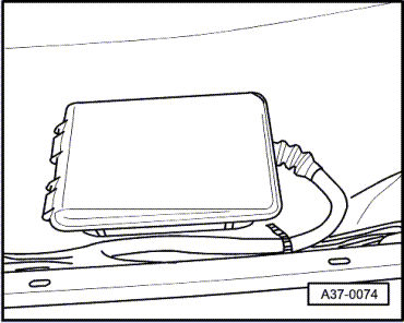
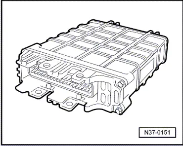
→ Fig.1    Location of automatic gearbox control unit -J217-

The control unit is located in front of the right-hand seat under the carpet in footwell.

 
N37-0450

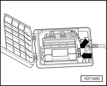
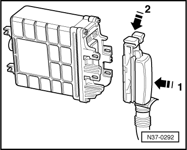
→ Fig.2    Removing automatic gearbox control unit -J217-

  • ‒ Loosen carpet and fold up.
  • ‒ Unclip control unit from box -arrows-
 
N37-0253
  • ‒ → Switch ignition off, release multi-pin connector in direction of arrow, and pull off control unit.

 
N37-0292

→ Fig.3    Installing automatic gearbox control unit -J217-

  • ‒ Fit multi-pin connector onto pins on control unit -J217 (1), then lock retainer on multi-pin connector (2).

Note:

When renewing automatic gearbox control unit, perform basic setting.

 
N37-0151

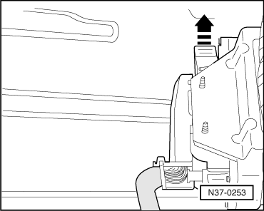
→ Fig.4    Engine control unit

Location: in electronics box in plenum chamber (left side)

Removing and installing control unit

=> Motronic Fuel Injection and Ignition (4-cylinder); Repair Group 24; Servicing Motronic injection system; Renewing engine control unit

=> Diesel Direct Injection and Glow Plug System (TDI 4-cylinder) ; Repair Group 23; Servicing diesel direct injection system; Renewing engine control unit

 
A24-0029

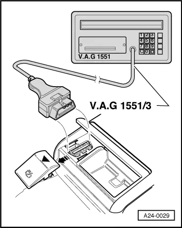
→ Fig.5    Diagnosis connections

Location: the diagnosis connection is located below the cover next to the rear ashtray (centre console).

  • ‒ Connect fault reader V.A.G 1551 and enter address word "02 Gearbox electronics" and advance until "Select function XX" indicated on display => from page 01-27.

 
N38-0068

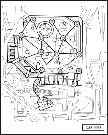
→ Fig.6    Valve body

Location: The valve body is bolted to the underside of gearbox housing inside the oil pan.

The solenoid valves -N88-, -N89-, -N90-, -N91-, -N92-, -N93- and -N94- are attached to the valve body.

Removing and installing valve body

=> Automatic Gearbox 01N; Repair Group 38; Removing and installing valve body

 
N38-0068

→ Fig. 7    Conductor strip with integrated gearbox oil temperature sender (ATF) -G93-

Location: The conductor strip is located in the oil pan on the valve body.

The conductor strip can be changed with gearbox installed without removing the valve body.

If the gearbox oil temperature sender (ATF) -G93- is defective, the conductor strip must be renewed at the same time since the sender is integral with the conductor strip and cannot be replaced separately.

Do not kink or damage the conductor strip.

Removing and installing conductor strip

=> Automatic Gearbox 01N; Repair Group 38; Removing and installing valve body

 
N37-0452

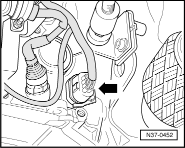
→ Fig.8    Multi-function switch -F125-

Location: the multi-function switch (arrow) is located on the rear of the gearbox (right side).

Removing and installing multi-function switch

  • ‒ Pull connector off multi-function switch.
  • ‒ Remove bolt and retainer.
  • ‒ Remove multi-function switch.
  • ‒ Renew seal.

Installation is performed in the reverse order.

  • ‒ Tighten bolt to10 Nm .
  • ‒ Check ATF level and top-up.

=> Automatic Gearbox 01N; Repair Group 37; Checking ATF level, changing ATF

 
N37-0453

→ Fig.9    Gearbox speed sender -G38-

Location: The gearbox speed sender is located left on top of gearbox.

Removing and installing gearbox speed sender

  • ‒ Pull connector off sender.
  • ‒ Remove bolt and pull sender out.
  • ‒ Renew seal.

Installation is performed in the reverse order.

  • ‒ Tighten bolt to 10 Nm.
 
N37-0454

→ Fig.10    Road speed sender -G68-

Location: The road speed sender is located right on top of gearbox.

Removing and installing road speed sender

  • ‒ Pull connector off sender.
  • ‒ Remove bolt and pull sender out.
  • ‒ Renew seal.

Installation is performed in the reverse order.

  • ‒ Tighten bolt to 10 Nm.
 
N37-0455

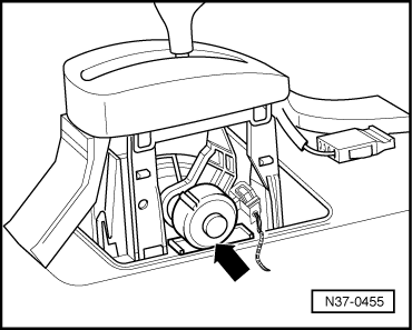
→ Fig.11    Selector lever lock solenoid -N110-

Location: The selector lever lock solenoid is located on selector lever (arrow).

Removing and installing selector lever lock solenoid

=> Automatic Gearbox 01N; Repair Group 37; Servicing shift mechanism

 
A23-0039

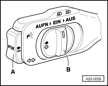
→ Fig.12    Cruise control system switch -E45-

Location: Cruise control switch is located on steering column switch.

Removing and installing cruise control switch

=> Electrical system; Repair Group 94; Servicing steering column switch

 
N37-0154

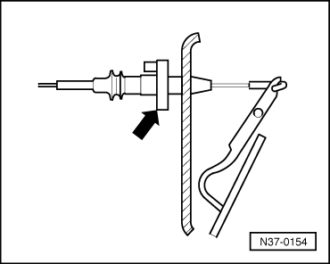
→ Fig.13    Kickdown switch -F8

Location in vehicles with petrol engine: integral with throttle cable, in plenum chamber behind bulkhead.

Location in vehicles with TDI engine: integral with accelerator position sender -G79.

Removing and installing kickdown switch

  • ‒ 4-cylinder fuel injection engine: to remove and install kickdown switch, remove and install throttle cable then adjust cable

=> 4-Cylinder fuel injection engine (5-valve), Mechanics ; Repair Group 20; Fuel supply; Servicing throttle cable (automatic gearbox)

  • ‒ 4-cylinder diesel direct injection engine: to remove and install kickdown switch, remove and install accelerator position sender -G79

=> 4-Cylinder diesel direct injection engine (TDI), Mechanics ; Repair Group 20

 
N37-0155

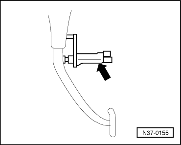
→ Fig.14    Brake light switch -F-

Location: Brake light switch (arrow) is located on pedal cluster.

Removing and installing brake light switch

=> Running Gear; Repair Group 46; Removing and installing pedal cluster; Servicing pedal cluster

Performing self-diagnosis > < Technical data of self-diagnosis