
A4 Mk1
|
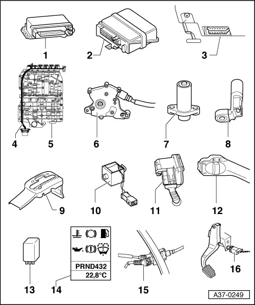
Electrical/electronic components and fitting locations
Electrical/electronic components and fitting locations
|
 |
|
|
|
|
|
|
|
|
|
|
|
|
|
|
|
|
|
|
=> Electrical System; Repair Group 94; Servicing steering column switch
=> "Current Flow Diagrams, Electrical Fault-finding and Fitting Locations" binder |
|
|
|
|
|
=> Running Gear; Repair Group 46; Removing and installing pedal cluster, servicing pedal cluster
|
 |
|
=> General Body Repairs; Repair Group 70; Trim Panels
|
 |
|
|
|
|
|
Installing: Install in reverse order. The following additional steps are required:
|
 |
|
|
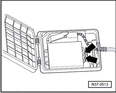
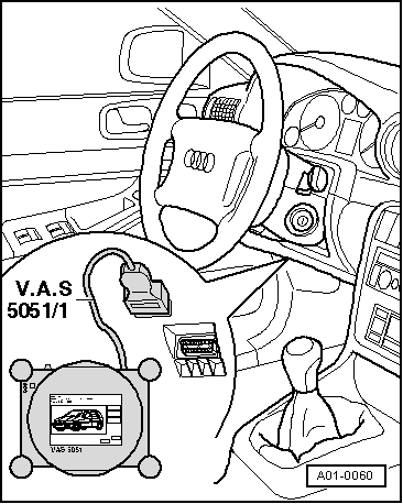
→ Fig.5 Diagnostic connection Fitting location: Diagnostic connection is located beneath knee restraint on left of steering wheel.
|
 |
|
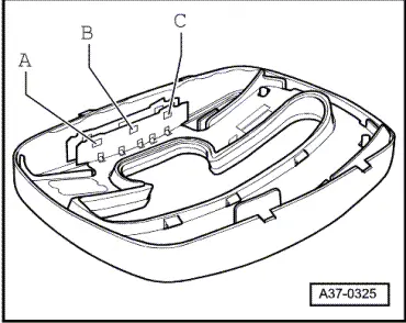
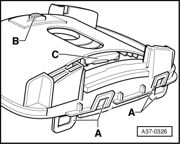
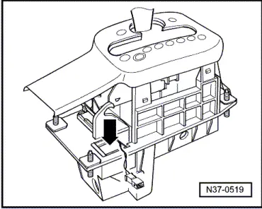
→ In the event of faults, start by checking whether magnet is properly attached to transverse slide -C- of masking panel and replace masking panel if necessary. Symbol panel with integrated printed circuit board is not to be replaced before checking wiring. On vehicles with Tiptronic sports steering wheel, the buttons on the steering wheel and their wiring must also be checked. Removing and installing Tiptronic switch -F189 => Automatic Gearbox 01V Front and Four-wheel Drive; Repair Group 37; Servicing shift mechanism |
 |
|
|
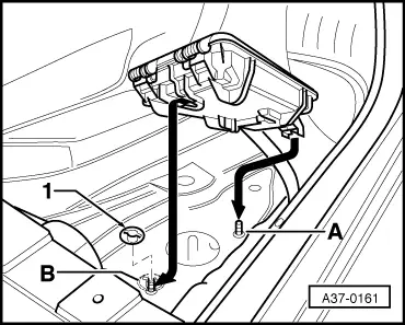
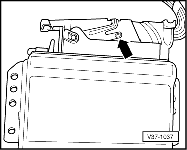
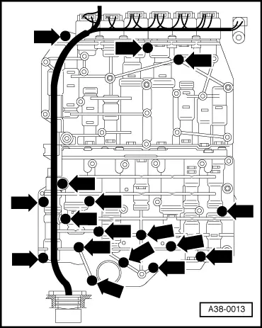
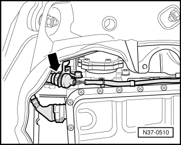
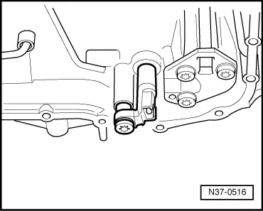
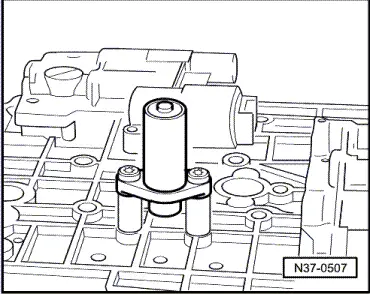
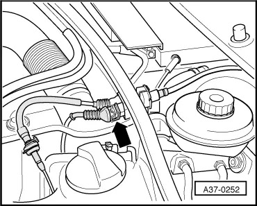
→ Fig.12 Selector lever lock solenoid -N110 Fitting location: Selector lever lock solenoid is located in shift mechanism -arrow-. Removing and installing selector lever lock solenoid => Automatic Gearbox 01V Front and Four-wheel Drive; Repair Group 37; Servicing shift mechanism |
 |
|
|
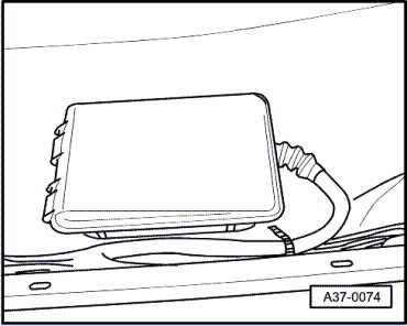
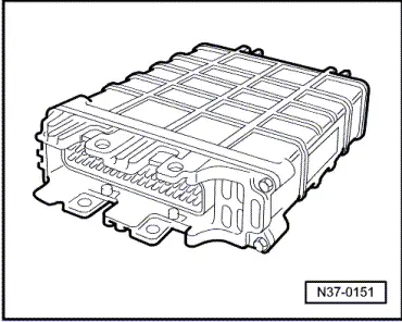
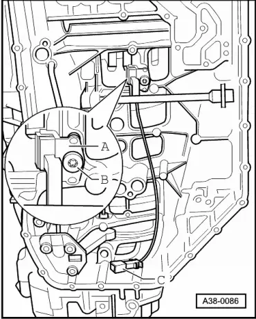
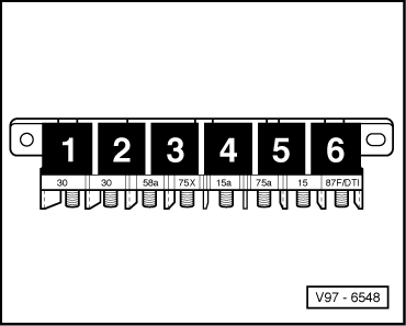
→ Fig.14 Starter inhibitor relay -J207 Fitting location: Relay is located in central electrics. Assignment => Current Flow Diagrams, Electrical Fault-finding and Fitting Locations binder |
 |
|
|
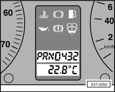
→ Fig.15 Selector lever position indicator -Y6 Fitting location: In dash panel insert Removing and installing selector lever position indicator => Electrical System; Repair Group 90; Servicing dash panel insert |
 |
|
|
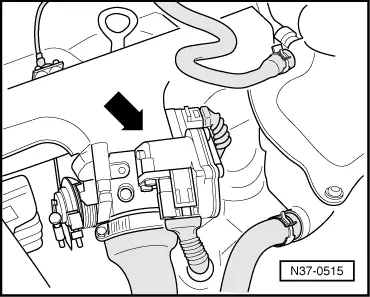
→ Fig.16 Kickdown switch -F8 Fitting location (petrol engines with no electronic throttle): Behind bulkhead in plenum chamber, integrated into throttle cable Fitting location (TDI engines and engines with electronic throttle): Kickdown switch is integrated into accelerator position sender (-G79, -G185). If accelerator position sender (-G79, -G185) is removed, engine control unit replaced or battery disconnected, adaption must be performed for switching point of kickdown switch on TDI engines and engines with electronic throttle. => Fuel Supply System - Petrol Engines; Repair Group 20 => Fuel Supply System - Diesel Engines; Repair Group 20 Removing and installing kickdown switch
|
 |
|
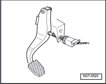
|
→ Fig.17 Brake light switch -F Fitting location: Brake light switch (arrow) is located at pedal cluster. Removing and installing brake light switch => Running Gear; Repair Group 46; Removing and installing pedal cluster, servicing pedal cluster Note: On engines with electronic throttle, brake light signal is transmitted via CAN bus from engine control unit to gearbox control unit. |