audi Workshop Repair Guides

Audi A4 Workshop Service and Repair Manuals

6-Speed manual gearbox 01E Four-wheel drive > < Checking wiring between 88-pin gearbox control unit and gearbox
Automatic Gearbox 01V Self-diagnosis
Electrical check
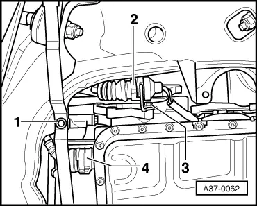
Checking multi-function switch -F125 (driving range sensor)

Notes:

  • ◆ Prior to electrical checking of multi-function switch, measured value block for multi-function switch must be checked , Display group number 004.
  • ◆ Make sure selector lever cable is properly adjusted.

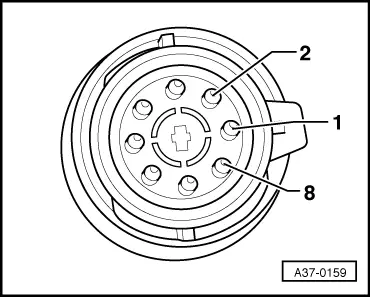
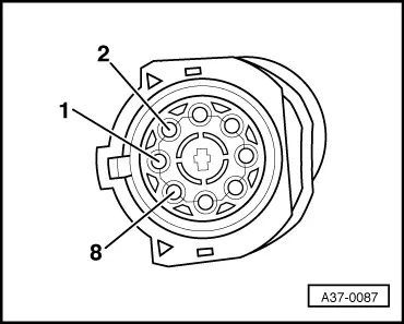
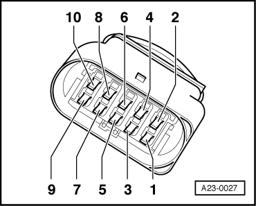
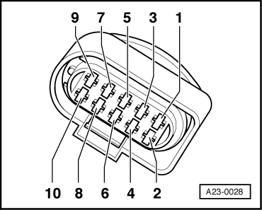
Use is made of two different multi-function switches:

1. Multi-function switch with 8-pin connector=>Checking, Page 01-315 onwards

2. Multi-function switch with 10-pin connector=>Checking, Page 01-326 onwards

Checking for multi-function switch with 8-pin connector

 
A37-0062

1. Checking operation

  • ‒ → Remove spring clip of 8-pin connector -2- from connector to cable/multi-function switch.
  • ‒ Unclip connector to multi-function switch from mount or unscrew holder together with connector from gearbox to provide better access to contacts in connector.

 
A37-0159
  • ‒ → Contact assignment at 8-pin connector of multi-function switch
    -F125 (to multi-function switch).
  • ‒ Make use of portable multimeter V.A.G 1526A or vehicle diagnostic, testing and information system VAS 5051.

Checking for gearbox with 8-pin connector at multi-function switch -F125

Select measuring range: Resistance measurement

Test step

Contacts at -F125

Testing of

▪ Test conditions
- Additional work

Specification

Measures if reading does not match specification

1

1 + 7
1 + 6

Multi-function switch -F125

▪ Ignition off
Selector lever set to
"P", "R", "N", "D", "4", "3" and "2"

Infinity
ω1)

- Check connector at multi-function switch for contact corrosion, ingress of water or loose fit

1 + 2

▪ Ignition off
Selector lever set to
"P", "N" and "D"

Less than 2ω


If necessary, adjust selector lever cable

- Selector lever set to
"R", "4", "3" and "2"

Infinity
ω1)

=> Automatic Gearbox 01V Front and Four-wheel Drive; Repair Group 37; Servicing shift mechanism

1 + 3

▪ Ignition off
Selector lever set to
"R", "N" and "4"

Less than 2ω

Continued

- Selector lever set to
"P", "D", "3" and "2"

Infinity
ω1)

- Replace multi-function switch -F125 => Page 01-27, Fig. 12

1)    Switch V.A.G 1526 to maximum ω range

Checking for gearbox with 8-pin connector at multi-function switch -F125

Select measuring range: Resistance measurement

Test step

Contacts at -F125

Testing of

▪ Test conditions
- Additional work

Specification

Measures if reading does not match specification

Continuation of

1

1 + 4

▪ Ignition off
Selector lever set to
"N", "D", "4" and "2"

Less than

- Check connector at multi-function switch for contact corrosion, ingress of water or loose fit

- Selector lever set to
"P", "R" and "3"

Infinity
ω1)

1 + 5

▪ Ignition off
Selector lever set to
"D", "4" and "3"

Less than
2 ω

- If necessary, adjust selector lever cable

- Selector lever set to
"P", "R", "N" and "2"

Infinity
ω1)

=> Automatic Gearbox 01V Front and Four-wheel Drive; Repair Group 37; Servicing shift mechanism

1 + 8

▪ Ignition off
Selector lever set to "R"

Less than

Continued

- Selector lever set to
"P", "N" "D", "4", "3" and "2"

Infinity
ω1)

- Replace multi-function switch -F125 => Page 01-27, Fig. 12

1)    Switch V.A.G 1526 to maximum ω range

Checking for gearbox with 8-pin connector at multi-function switch -F125

Select measuring range: Resistance measurement

Test step

Contacts at -F125

Testing of

▪ Test conditions
- Additional work

Specification

Measures if reading does not match specification

Continuation of

1

6 + 7

P/N signal of multi-function switch

▪ Ignition off
Selector lever set to "R", "D", "4", "3" and "2"

Infinity
ω1)

- Replace multi-function switch -F125 => Page 01-27, Fig. 12

▪ Ignition off
Selector lever set to "P" "N"

Less than

P/N signal for engine control unit is to be checked

1)    Switch V.A.G 1526 to maximum ω range

Notes:

  • ◆ If functional check is OK, check power supply of multi-function switch => Page 01-319
 
A37-0062

2. Checking power supply of 8-pin multi-function switch

  • ‒ → Remove spring clip of 8-pin connector -2- from connector to cable/multi-function switch.

Checking is performed at connector with spring clip (sockets) to gearbox control unit.

 
A37-0087
  • ‒ → Contact assignment at 8-pin connector of multi-function switch
    -F125 (to gearbox control unit).
  • ‒ Make use of portable multimeter V.A.G 1526A or vehicle diagnostic, testing and information system VAS 5051.

Select measuring range:
Voltage measurement

Connector contacts (socket)

▪ Test conditions

Specification

1 + 6

▪ Ignition on

approx. battery voltage

  • ‒ If readings do not match specifications, use current flow diagram to check fuses and wiring and eliminate faults.

Notes:

If functional check and power supply of multi-function switch are OK, check wiring from automatic gearbox control unit -J217 to multi-function switch -F125 => Page 01-321

 
V37-1037

3. Checking wiring from automatic gearbox control unit -J217 to 8-pin multi-function switch -F125

  • ‒ → For all test steps, switch off ignition, unplug multi-pin connector from automatic gearbox control unit -J217 (control unit is located in front of right seat beneath cover in footwell => Page 01-6) and connect test box V.A.G 1598/20 to wiring harness connector.

 
A37-0062
  • ‒ → Connect the two 8-pin connectors -2- to multi-function switch (as illustrated).
  • ‒ Make use of portable multimeter V.A.G 1526A or vehicle diagnostic, testing and information system VAS 5051.

Checking for gearbox with 8-pin connector at multi-function switch -F125

Select measuring range: Voltage measurement

Test step

V.A.G 1598/20

Testing of

▪ Test conditions
- Additional work

Specification

Measures if reading does not match specification

1

36 + 34
36 + 6

Multi-function switch -F125

▪ Ignition on
Selector lever set to "P", "N" and "D"

approx. battery voltage

- Check connector at multi-function switch for contact corrosion

- Selector lever set to "R", "4", "3" and "2"

Less than
1 V

- Use current flow diagram to check wiring

8 + 34
8 + 6

▪ Ignition on
Selector lever set to "R", "N" and "4"

approx. battery voltage

- Check fuses
Check supply voltage of
-F125 => Page 01-319

- Selector lever set to "P", "D", "3" and "2"

Less than
1 V

- Check wiring of control unit to 8-pin connector => Page 01-310

37 + 34
37 + 6

- Selector lever set to "N", "D", "4" and "2"

approx. battery voltage

- Selector lever set to "P", "R" and "3"

Less than
1 V

9 + 34
9 + 6

- Selector lever set to "D", "4" and "3"

approx. battery voltage

- Selector lever set to "P", "R", "N" and "2"

Less than
1 V

Checking for gearbox with 8-pin connector at multi-function switch -F125

Select measuring range: Resistance measurement

Test step

V.A.G 1598/20

Testing of

▪ Test conditions
- Additional work

Specification

Measures if reading does not match specification

2

36 + 8

Multi-function switch -F125

▪ Ignition off
Selector lever set to "N"

Less than
26 ω

- Check connector at multi-function switch for contact corrosion

- Selector lever set to "P", "R", "D", "4", "3", "2"

Infinity
ω1)

- Check wiring from 88-pin control unit to 8-pin connector => Page 01-310

37 + 9

▪ Ignition off
Selector lever set to "D" and "4"

Less than
26 ω

- Perform test steps 6 and 27

- Fuse 31 disconnected 2)
Selector lever set to "P", "R", "N", "3" and "2"

Infinity
ω1)

37 + 36

▪ Ignition off
Selector lever set to "N" and "D"

Less than
26 ω

- Selector lever set to "P", "R", "4", "3" and "2"

Infinity
ω1)

1)    Switch V.A.G 1526 to maximum ω range

2)    Fuse for multi-function switch -F125 power supply

 
A37-0062

4. Checking wiring from automatic gearbox control unit -J217 to 8-pin connector at multi-function switch

  • ‒ Switch off ignition.
  • ‒ → Remove spring clip of 8-pin connector -2- from connector to cable/multi-function switch.

 
A37-0087
  • ‒ → Contact assignment at 8-pin connector of multi-function switch
    -F125 (sockets to gearbox control unit).

Checking is performed between 8-pin connector with spring clip (sockets) and test box V.A.G 1598/20 at control unit connector.

  • ‒ Make use of portable multimeter V.A.G 1526A or vehicle diagnostic, testing and information system VAS 5051.

Checking for gearbox with 8-pin connector at multi-function switch -F125

Connector contact

Test box V.A.G 1598/20, socket

Specification

Measures if reading does not match specification

1

54, 55

≤ 1.5 ω

- Use current flow diagram to eliminate open circuit in wiring

2

36

≤ 1.5 ω

Check connector for:

3

8

≤ 1.5 ω

- Contact corrosion

4

37

≤ 1.5 ω

- Ingress of water

5

9

≤ 1.5 ω

- Leakage

6

6, 34

≤ 1.5 ω

7

P/N signal for engine control unit

≤ 1.5 ω

8

Refer to reversing lights

≤ 1.5 ω

Checking for multi-function switch with 10-pin connector

 
A37-0062

1. Checking operation

  • ‒ → Unplug 10-pin connector -2- to multi-function switch.
  • ‒ Unclip connector to multi-function switch from mount or unscrew holder together with connector from gearbox to provide better access to contacts in connector.

 
A23-0027
  • ‒ → Contact assignment at 10-pin connector of multi-function switch
    -F125 (to multi-function switch).
  • ‒ Make use of portable multimeter V.A.G 1526A or vehicle diagnostic, testing and information system VAS 5051.

Checking for gearbox with 10-pin connector at multi-function switch -F125

Select measuring range: Resistance measurement

Test step

Contacts at -F125

Testing of

▪ Test conditions
- Additional work

Specification

Measures if reading does not match specification

1

7 + 9
7 + 10
1 + 7
1 + 8
1 + 9
1 + 10

Multi-function switch -F125

▪ Ignition off

Infinity
ω1)

- Check connector at multi-function switch for contact corrosion, ingress of water or loose fit

1 + 2

▪ Ignition off
Selector lever set to "P", "N" and "D"

Less than


If necessary, adjust selector lever cable

- Selector lever set to "R", "4", "3", "2"

Infinity
ω1)

=> Automatic Gearbox 01V Front and Four-wheel Drive; Repair Group 37; Servicing shift mechanism


Continued

1 + 3

▪ Ignition off
Selector lever set to "R", "N" and "4"

Less than

- Replace multi-function switch -F125 => Page 01-27, Fig. 12


- Selector lever set to "P", "D", "3" and "2"

Infinity
ω1)

1)    Switch V.A.G 1526 to maximum ω range

Select measuring range: Resistance measurement

Test step

Contacts at -F125

Testing of

▪ Test conditions
- Additional work

Specification

Measures if reading does not match specification

Continuation of

1 + 4

▪ Ignition off
Selector lever set to "N", "D", "4" and "2"

Less than

- Check connector at multi-function switch for contact corrosion, ingress of water or loose fit

1

- Selector lever set to "P", "R" and "3"

Infinity
ω1)

- If necessary, adjust selector lever cable

1 + 5

▪ Ignition off
Selector lever set to "D", "4" and "3"

Less than

=> Automatic Gearbox 01V Front and Four-wheel Drive; Repair Group 37; Servicing shift mechanism

- Selector lever set to "P", "R", "N" and "2"

Infinity
ω1)

9 + 10

▪ Ignition off
Selector lever set to "P", "N"

Less than

- Replace multi-function switch -F125 => Page 01-27, Fig. 12

- Selector lever set to "R", "D", "4", "3" and "2"

Infinity
ω1)

8 + 7

▪ Ignition off
Selector lever set to "R"

Less than

- Selector lever set to "P", "4" "3" "2", "N" and "D"

Infinity
ω1)

1)    Switch V.A.G 1526 to maximum ω range

  • ◆ If functional check is OK, check power supply of multi-function switch => Page 01-319
 
A37-0062

2. Checking power supply of 10-pin multi-function switch

  • ‒ → Unplug 10-pin connector -2- to multi-function switch.

Checking is performed at connector (sockets) to gearbox control unit.

 
A37-0087
  • ‒ → Contact assignment at 10-pin connector of multi-function switch
    -F125 (sockets to gearbox control unit).
  • ‒ Make use of portable multimeter V.A.G 1526A or vehicle diagnostic, testing and information system VAS 5051.

Select measuring range:
Voltage measurement

Connector contacts (socket)

▪ Test conditions

Specification

1 + 10
7 + 10

▪ Ignition on

approx. battery voltage

  • ‒ If readings do not match specifications, use current flow diagram to check fuses and wiring and eliminate faults.

Notes:

If functional check and power supply of multi-function switch are OK, check wiring from automatic gearbox control unit -J217 to multi-function switch -F125 => Page 01-331

 
V37-1037

3. Checking wiring from automatic gearbox control unit -J217 to 10-pin multi-function switch -F125

  • ‒ → For all test steps, switch off ignition, unplug multi-pin connector from automatic gearbox control unit -J217 (control unit is located in front of right seat beneath cover in footwell => Page 01-6) and connect test box V.A.G 1598/20 to wiring harness connector.

 
A37-0062
  • ‒ → Connect the two 10-pin connectors -2- to multi-function switch (as illustrated).
  • ‒ Make use of portable multimeter V.A.G 1526A or vehicle diagnostic, testing and information system VAS 5051.

Checking for gearbox with 10-pin connector at multi-function switch -F125

Select measuring range: Voltage measurement

Test step

V.A.G 1598/20

Testing of

▪ Test conditions
- Additional work

Specification

Measures if reading does not match specification

1

54 + 34
54 + 6
55 + 34
55 + 6

Voltage supply

▪ Ignition on

approx. battery voltage

- Check fuses
Use current flow diagram to check wiring

2

36 + 34
36 + 6

Multi-function switch -F125

▪ Ignition on
Selector lever set to "P", "N" and "D"

approx. battery voltage

- Check connector at multi-function switch for contact corrosion

- Selector lever set to "R", "4", "3" and "2"

Less than 1 V

- Use current flow diagram to check wiring

8 + 34
8 + 6

▪ Ignition on
Selector lever set to "R", "N" and "4"

approx. battery voltage

- Check power supply of multi-function switch => Page 01-329

Continued

- Selector lever set to "P", "D", "3" and "2"

Less than 1 V

- Check control unit wiring to 10-pin connector => Page 01-336

Checking for gearbox with 10-pin connector at multi-function switch -F125

Select measuring range: Voltage measurement

Test step

V.A.G 1598/20

Testing of

▪ Test conditions
- Additional work

Specification

Measures if reading does not match specification

Continuation of

37 + 34
37 + 6

- Selector lever set to "N", "D", "4" and "2"

approx. battery voltage

- Check connector at multi-function switch for contact corrosion

2

- Selector lever set to "P", "R" and "3"

Less than 1 V

- Use current flow diagram to check wiring

9 + 34
9 + 6

- Selector lever set to "D", "4" and "3"

approx. battery voltage

- Check power supply of multi-function switch => Page 01-329

- Selector lever set to "P", "R", "N" and "2"

Less than 1 V

- Check control unit wiring to 10-pin connector => Page 01-336

Checking for gearbox with 10-pin connector at multi-function switch -F125

Select measuring range: Resistance measurement

Test step

V.A.G 1598/20

Testing of

▪ Test conditions
- Additional work

Specification

Measures if reading does not match specification

3

55 + 54

Multi-function switch -F125

▪ Ignition off

≤ 1.5 ω

55 + 36

▪ Ignition off
Selector lever set to "P", "N" and "D"

Less than 26 ω

- Check connector at multi-function switch for contact corrosion

- Selector lever set to "R", "4", "3" and "2"

Infinity
ω1)

- Check wiring from 88-pin control unit to 10-pin connector => Page 01-310

55 + 8

▪ Ignition off
Selector lever set to "R", "N" and "4"

Less than 26 ω

- Perform test steps 6 and 27

Continued

- Selector lever set to "P", "D", "3" and "2"

Infinity
ω1)

Checking for gearbox with 10-pin connector at multi-function switch -F125

Select measuring range: Resistance measurement

Test step

V.A.G 1598/20

Testing of

▪ Test conditions
- Additional work

Specification

Measures if reading does not match specification

Continuation of

7

55 + 37

Multi-function switch -F125

▪ Ignition off
Selector lever set to
"N", "D", "4" and "2"

≤ 1.5 ω

- Check connector at multi-function switch for contact corrosion

- Selector lever set to "P", "R" and "3"

Infinity
ω1)

- Check wiring from 88-pin control unit to 10-pin connector => Page 01-310

55 + 9

▪ Ignition off
Selector lever set to
"D", "4" and "3"

Less than
26 ω

- Selector lever set to
"P", "R", "N" and "2"

Infinity
ω1)

1)    Switch V.A.G 1526 to maximum ω range

2)    Fuse for multi-function switch -F125 power supply

 
A37-0062

4. Checking wiring from automatic gearbox control unit -J217 to 10-pin connector at multi-function switch

  • ‒ Switch off ignition.
  • ‒ → Unplug 10-pin connector -2- to multi-function switch.

 
A23-0028
  • ‒ → Contact assignment at 10-pin connector of multi-function switch
    -F125 (sockets to gearbox control unit).

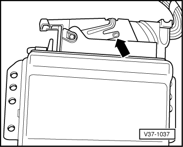
Checking is performed between 10-pin connector (sockets) and test box V.A.G 1598/20 at control unit connector.

  • ‒ Make use of portable multimeter V.A.G 1526A or vehicle diagnostic, testing and information system VAS 5051.

Checking for gearbox with 10-pin connector at multi-function switch -F125

Connector contact

Test box V.A.G 1598/20, socket

Specification

Measures if reading does not match specification

1

54, 55

≤ 1.5 ω

- Use current flow diagram to eliminate open circuit in wiring

2

36

≤ 1.5 ω

Check connector for:

3

8

≤ 1.5 ω

- Contact corrosion

4

37

≤ 1.5 ω

- Ingress of water

5

9

≤ 1.5 ω

- Leakage

6 : Not used

7

54, 55

≤ 1.5 ω

8

Refer to reversing lights

≤ 1.5 ω

9

P/N signal for engine control unit

≤ 1.5 ω

10

6, 34

≤ 1.5 ω

6-Speed manual gearbox 01E Four-wheel drive > < Checking wiring between 88-pin gearbox control unit and gearbox