
A4 Mk1
 |
|
|
=> Current Flow Diagrams, Electrical Fault-finding and Fitting Locations binder Sequence of operations
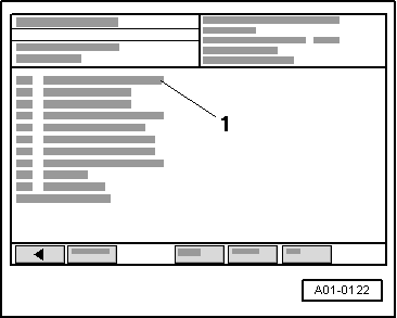
→ Display on VAS 5051:
|
 |
|
|
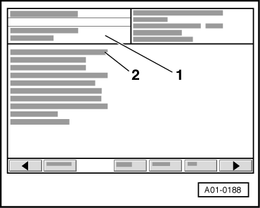
→ Display on VAS 5051:
|
|
|
|
Notes: Control element fitting locations => Page 01-6 Control elements can now be actuated in the sequence described on the preceding pages. Next control element can be selected by pressing ▸ key until control element test is completed. Prior to restarting final control diagnosis, engine must be started and ignition switched off and on again. Operation of the first four control elements (solenoid valves 1 -N88, 2 -N89, 3 -N90 and selector lever lock solenoid=>-N110) is checked acoustically during final control diagnosis. Background noise should be avoided during the acoustic check as the switching noise (clicking) of the control elements is very quiet.
None of the other control elements are audible on actuation. Certain special features of these other control elements are described in the following. |
|
|
|
→ Display on VAS 5051:
Notes:
|
|
|
→ Display on VAS 5051:
|
|
|
|
→ Display on VAS 5051:
Prior to restarting final control diagnosis, engine must be started and ignition switched off and on again. |